
D
Propulsion Taxonomy: Comments on Propulsion Fundamentals
The purpose of this taxonomy, which is a generalization of Zwicky’s idea (Zwicky, 1959), is to suggest that there are many unexplored ideas in the realm of aircraft propulsion. As with any taxonomy, not all the ideas are fruitful. Some can be immediately rejected as violating physical principles, and other ideas may not be capable of developing a suitable energy density. Nevertheless, a simplified taxonomy of aircraft propulsion provides a means of sorting and defining a large number of propulsion devices, some of which are in use, some of which may be practical following an adequate level of research, and some of which may never be practical.
Assuming an isentropic compression and expansion phase of the cycle, the committee identified 10 fundamental cycles that use fuel to provide thrust, shaft power, or electricity as an output (see Table D-1). Nine of these are thermodynamic in nature and the tenth converts fuel directly to electricity. This is the fuel cell. Batteries have intentionally been omitted because considerable development seems to be neces
TABLE D-1 Fundamental Thermodynamic Cycles (nonregenerative)a
sary before this power source can be applied to the propulsion of common as opposed to niche airplanes.
Alternating-current electric motors are relatively heavy. New magnetic materials provide lighter weight direct-current motors. This may or may not be the most immediate application of power from fuel cells. The heat added by a resistance heater is confined to a thermal boundary layer, which like all boundary layers is quite thin. Any attempt to emulate volumetric heating requires a relatively dense distribution of resistive elements and thus a sizable pressure drop. For this reason a fuel cell seems unlikely to be used to power a resistance heater to replace the combustor in an aircraft engine. However, the power from a fuel cell might be used for a volumetric heating process using a plasma, a laser, or a microwave breakdown process. If room-temperature superconductivity becomes a reality, a rotating electromagnetic wave in the nacelle could be used to suspend and drive a fan. The power for this arrangement could conceivably be derived from a fuel cell of the future.
The first column of a propulsion taxonomy (see Table D-2) could be defined by 10 items, the 9 cycles given in Table D-1 plus fuel cells. The second column would have two items: continuous and intermittent. Thus,
|
Cycle |
Operation |
||
|
1 |
Isothermal-isothermal |
1 |
Continuous |
|
2 |
Isothermal-isovolume |
2 |
Intermittent |
|
3 |
Isothermal-isobaric |
|
|
|
4 |
Isovolume-isothermal |
|
|
|
5 |
Isovolume-isovolume |
|
|
|
6 |
Isovolume-isobaric |
|
|
|
7 |
Isobaric-isothermal |
|
|
|
8 |
Isobaric-isovolume |
|
|
|
9 |
Isobaric-isobaric |
|
|
|
10 |
Fuel cell |
|
|
TABLE D-2 Matrix Summary of Propulsion Taxonomy
|
Cyclea |
Operation |
Pressurization |
Energy release |
Propulsion |
|||||
|
1 |
Isothermal-isothermal |
1 |
Continuous |
1 |
Mechanical |
1 |
Oxidation (combustion) |
1 |
Propeller |
|
2 |
Isothermal-isovolume |
2 |
Intermittent |
2 |
Self-pressurized |
|
2 |
Turbofan |
|
|
3 |
Isothermal-isobaric |
|
|
3 |
Both |
2 |
Electrochemical (fuel cell) |
3 |
Turbofan and afterburner |
|
4 |
Isovolume-isothermal |
|
|
|
|
|
|
||
|
5 |
Isovolume-isovolume |
|
|
|
|
3 |
Photochemical (photosynthesis) |
4 |
Turbojet |
|
6 |
Isovolume-isobaric |
|
|
|
|
|
5 |
Ramjet |
|
|
7 |
Isobaric-isothermal |
|
|
|
|
4 |
Photoelectric (solar cell) |
6 |
Rocket |
|
8 |
Isobaric-isovolume |
|
|
|
|
|
7 |
Turbojet and afterburner |
|
|
9 |
Isobaric-isobaric |
|
|
|
|
5 |
Photodirect (laser/electromagnetic heating) |
|
|
|
10 |
Fuel cell |
|
|
|
|
|
8 |
Pulse-jet (pulse detonation engine) |
|
|
aCycle name describes methods of heat absorption and heat rejection, respectively. |
|||||||||
Selecting one item from the first column and one from the second column defines, in an elemental way, a family of 20 power plants. However, the continuous isothermal and isovolume cycles can be immediately ruled out as physically impossible because in the steady state the fluid is forced to move uphill against the total pressure gradient. This leaves 12 potential power plants (10 intermittent and 2 continuous: isobaric-isobaric and fuel cell). The next column of the taxonomy is pressurization:
|
Pressurization |
|
|
1 |
Mechanical |
|
2 |
Self-pressurized |
|
3 |
Both |
These three entries create a total of 36 options (30 intermittent and 6 continuous). Consider next energy release processes from fuel. The terms in parentheses are common names for the processes.
|
Energy Release |
|
|
1 |
Oxidation (combustion) |
|
2 |
Electrochemical (fuel cell) |
|
3 |
Photochemical (photosynthesis) |
|
4 |
Photoelectric (solar cell) |
|
5 |
Photodirect (laser/electromagnetic heating) |
|
Etc. |
|
Recombination of excited molecular and atomic states, free radicals, and antimatter recombination are included in the term “etc.” but are not further considered because of the problems of storing the fuels. Nuclear energy release is excluded because of the weight of shielding material and radioactive hazards. With this exclusion, we now have five more options, which creates a total of 180 possible devices. Photochemical, photoelectric, and photodirect systems arguably possess a low energy density and in all likelihood will only find niche applications. Setting aside low-power-density processes reduces the number of options to 72 (60 intermittent and 12 continuous).
Propulsion mechanism is the next area for consideration.
|
Propulsion |
|
|
1 |
Propeller |
|
2 |
Turbofan |
|
3 |
Turbofan + afterburner |
|
4 |
Turbojet |
|
5 |
Ramjet |
|
6 |
Rocket |
|
7 |
Turbojet + afterburner |
|
8 |
Pulse-jet (pulse detonation engine) |
These eight items provide one intermittent propulsion option and seven continuous propulsion options, one of which (the propeller) can also be used with intermittent cycles. This results in 204 options (2 × 60 + 7 × 12), which is quite a large number.
COMMENTS
Both the constant temperature and constant volume heat absorption (or combustion) cycles are usually intermittent (pulsed). Intermittent processes have the potential to operate at higher temperatures and reasonable wall temperatures because the wall can be cooled during the part of the cycle when no heat is applied. However, in practice some of this heat is lost and reduces efficiency. Further, while intermittent cycles have a high efficiency per pulse, the average efficiency is lower because power is available only part of the time.
The fuel cell could require a precompression of fuel depending on the fuel storage mechanism. The fuel cell has the
potential to be isothermal and is thus quite attractive. Coupled to a superconducting electric motor, it could have a very high efficiency with low hydrocarbon emissions. The water vapor emissions can be reduced to zero, though at some expense in weight.
System weight and thermal efficiency are the fundamental system issues. The three curves in Figure D-1 show cycle efficiency as a function of the ratio of the heat rejection temperature (T2) to the heat absorption temperature (T1). The Carnot cycle is clearly the most efficient, with the Otto cycle second and the Brayton cycle the least efficient. The comparison is somewhat misleading, however, since efficiencies for the Carnot and Otto cycles are per pulse and not the average over the cycle. Carnot and Otto cycle efficiencies are somewhat lower in practice. An additional curve in Figure D-1 shows the efficiency of the Otto cycle if power is produced during only half the cycle.
The isobaric cycles can be continuous or intermittent since the pressure falls during combustion processes. Each process has its limitations. For example, the efficiency of the Brayton cycle is limited by material limits. That is, the compressor exit temperature is limited by high temperature material properties. Nevertheless, the continuous or open Brayton cycle provides a high power density and a relatively simple structure.
Relaxing the constraint on adiabatic compression and expansion (e.g., by using regeneration) almost doubles the number of options. For example, it may be possible for heat
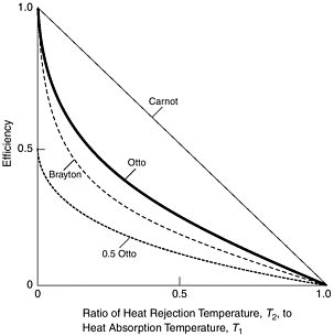
FIGURE D-1 Thermal efficiency of the Otto, Brayton, and Carnot cycles.
removed during compression to be added during expansion in the turbine. With the exceptions described above, the current state of the art for heat exchanger technology is based on surface heat removal, not volume heat removal. The thermal boundary layer is thin even in an axial flow compressor, meaning the heat exchanger is likely to be heavy and create additional pressure losses. Hence until a volumetric heat exchange process is invented, the regenerative part of a modified Brayton cycle seems impractical.
Also, a cooling system upstream of the compressor could inject mist into the air stream. This would have two advantages: The stream would be cooled by evaporation and the total pressure would be increased. This is Ascher Shapiro’s aerothermo compressor. It might even be possible to inject the mist ahead of each compressor rotor and stator blade. In principle the cooling could be adjusted such that the temperature remains constant during compression. In practice, it may be possible to increase the effective compressor efficiency while reducing compressor outlet temperature by 50 to 150 °F. Another option would be to allow combustion in a suitably designed turbine stage, so that heat could be added in a more nearly isothermal fashion. This modified Brayton cycle seems attractive enough to warrant further research.
In summary, there seem to be a large number of alternative propulsion schemes. However, at present few alternatives seem to be practical; only a very few, including modified Brayton cycle engines, seem to warrant more than passing attention.
REFERENCE
Zwicky, F. 1959. Future Prospects of Jet Propulsion. Volume XII, Section L, Jet Propulsion Engines: High Speed Aerodynamics and Propulsion. Princeton, N.J.: Princeton University Press.


