
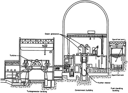
FIGURE D.1 A PWR in a large dry containment. SOURCE: Modified from Duderstadt and Hamilton (1976, Figure 3–4).
The dry well is connected by large ducts to the wet well, a large toroidal (i.e., doughnut-shaped) part of the containment that is partially filled with water. Gas and steam releases from an accident in the dry well would be passed through the connecting ducts into the water in the wet well, cooling the gas and condensing the steam to mitigate the accident pressure rise in the containment. The containment building Mark II BWR is similar to the Mark I except that in the Mark II containment the conical dry well is directly above the cylindrical wet well. Nine Mark II reactors are still operating in the United States. In the Mark III, the dry well around the reactor vessel is vented to the top of a cylindrical wet well that surrounds it.
Four Mark III BWRs are currently operating. The entire dry well-wet well system is contained within a large steel containment shell and a concrete shield building.
D.3.3 Reactor Fuel and Reactor Control
TABLE D.1 presents the range of dimensions and weights for a wide variety of the LWR fuel assemblies used in the operating reactors. The spent fuel pools and the dry storage systems used at a reactor must be tailored to the specific fuel design for that reactor.

