


Below is the uncorrected machine-read text of this chapter, intended to provide our own search engines and external engines with highly rich, chapter-representative searchable text of each book. Because it is UNCORRECTED material, please consider the following text as a useful but insufficient proxy for the authoritative book pages.
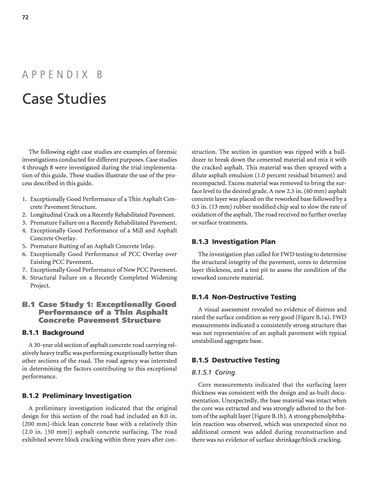
72 The following eight case studies are examples of forensic investigations conducted for different purposes. Case studies 4 through 8 were investigated during the trial implementa- tion of this guide. These studies illustrate the use of the pro- cess described in this guide. 1. Exceptionally Good Performance of a Thin Asphalt Con- crete Pavement Structure. 2. Longitudinal Crack on a Recently Rehabilitated Pavement. 3. Premature Failure on a Recently Rehabilitated Pavement. 4. Exceptionally Good Performance of a Mill and Asphalt Concrete Overlay. 5. Premature Rutting of an Asphalt Concrete Inlay. 6. Exceptionally Good Performance of PCC Overlay over Existing PCC Pavement. 7. Exceptionally Good Performance of New PCC Pavement. 8. Structural Failure on a Recently Completed Widening Project. B.1 Case Study 1: Exceptionally Good Performance of a Thin Asphalt Concrete Pavement Structure B.1.1 Background A 30-year old section of asphalt concrete road carrying rel- atively heavy traffic was performing exceptionally better than other sections of the road. The road agency was interested in determining the factors contributing to this exceptional performance. B.1.2 Preliminary Investigation A preliminary investigation indicated that the original design for this section of the road had included an 8.0 in. (200 mm)-thick lean concrete base with a relatively thin (2.0 in. [50 mm]) asphalt concrete surfacing. The road exhibited severe block cracking within three years after con- struction. The section in question was ripped with a bull- dozer to break down the cemented material and mix it with the cracked asphalt. This material was then sprayed with a dilute asphalt emulsion (1.0 percent residual bitumen) and recompacted. Excess material was removed to bring the sur- face level to the desired grade. A new 2.5 in. (60 mm) asphalt concrete layer was placed on the reworked base followed by a 0.5 in. (13 mm) rubber modified chip seal to slow the rate of oxidation of the asphalt. The road received no further overlay or surface treatments. B.1.3 Investigation Plan The investigation plan called for FWD testing to determine the structural integrity of the pavement, cores to determine layer thickness, and a test pit to assess the condition of the reworked concrete material. B.1.4 Non-Destructive Testing A visual assessment revealed no evidence of distress and rated the surface condition as very good (Figure B.1a). FWD measurements indicated a consistently strong structure that was not representative of an asphalt pavement with typical unstabilized aggregate base. B.1.5 Destructive Testing B.1.5.1 Coring Core measurements indicated that the surfacing layer thickness was consistent with the design and as-built docu- mentation. Unexpectedly, the base material was intact when the core was extracted and was strongly adhered to the bot- tom of the asphalt layer (Figure B.1b). A strong phenolphtha- lein reaction was observed, which was unexpected since no additional cement was added during reconstruction and there was no evidence of surface shrinkage/block cracking. A p p e n d i x B Case Studies
73 B.1.5.2 Test Pit The asphalt layer showed remarkably little oxidation and brittleness (Figure B.1c). The DCP did not penetrate the base layer, indicating a strongly cemented material. Excavation of the base layer revealed large lumps (4.0 in. [100 mm]) of the original base strongly bound to the rest of the material. A strong phenolphthalein reaction was observed over the entire depth of the reworked layer (Fig- ure B.1d). A scanning electron microscope study showed new calcite crystal growth on freshly exposed surfaces indicating that re-cementation of the previously cemented material was still occurring. B.1.6 Conclusion The exceptionally good performance was attributed to a combination of: ⢠Re-cementation of the reworked material, ⢠The use of diluted asphalt emulsion as a compaction aid, ⢠The presence of large aggregate (i.e., previously cemented) base materials, and ⢠The application of a surface treatment (rubber modified chip seal), which slowed the rate of oxidation of the asphalt concrete. B.2 Case Study 2: Longitudinal Crack on a Recently Rehabilitated Pavement B.2.1 Background A single straight longitudinal crack developed within one year after rehabilitation of a distressed asphalt concrete pavement using full-depth reclamation with foamed asphalt and portland cement (Figure B.2a). Apart from the crack, the road was per- forming well. The road agency, which had not built many full- depth reclamation projects with foamed asphalt/cement, was interested in determining the cause of the crack and whether this type of rehabilitation was appropriate for future projects. B.2.2 Preliminary Investigation A preliminary investigation indicated no apparent reason for the crack. The portland cement content was 1.0 percent, which was unlikely to result in shrinkage cracks. Construction qual- ity control was carried out according to the specifications. B.2.3 Investigation Plan An initial investigation plan called for a visual assessment and FWD testing on either side of the crack to identify any differences in structural integrity. a) Surface condition (no distress) b) Intact core c) Surface layer evaluation d) Phenolphthalein reaction Subbase Base AC Chip seal Phenolphthalein reaction on base Chip seal 1.0 in AC (25 mm AC) 1.4 in. AC (35 mm AC) Figure B.1. Investigation photographs for Case Study 1.
74 B.2b) suggesting no problems with the asphalt concrete. The crack was vertical suggesting some association with the recycler overlap. An expert opinion regarding the cause of the crack was sought and after discussion and observations of a nearby full- depth reclamation project, it was concluded that the crack was caused by shrinkage due to an excess of cement that accumu- lated under the skirt of the recycler (Figure B.2c), resulting in a narrow band of excessively stiff material. B.2.6 Conclusion The longitudinal crack was attributed to the inadequate spreading of excess cement on the edge of the recycler pass. Rec- ommendations from the investigation included requiring the contractor to control cement spreading and to rake any excess cement windrows prior to overlap passes with the recycler. B.2.4 Non-Destructive Testing The visual assessment and FWD testing identified no apparent cause for the crack. However, the crack was aligned with the approximate edge of the first pass of the recycler. One member of the team, who had observed construction, recalled that recycler passes had sufficient overlap and that the compaction sequence was correctly followed. The inves- tigation team then recommended a test pit to observe the underlying materials. B.2.5 Destructive Testing B.2.5.1 Test Pit A test pit across the crack revealed that the crack initiated approximately at mid-depth in the reclaimed layer (Figure a) Longitudinal crack on surface b) Vertical crack to mid point in reclaimed base c) Active filler windrow on edge of reclaimer path Active filler windrow Windrow covered by fine material Figure B.2. Investigation photographs for Case Study 2.
75 ing under soaked conditions and that the active filler content may have been too low. B.3.3 Investigation Plan An initial investigation plan called for a visual assessment and FWD testing along the project to identify problems areas requiring additional investigation. B.3.4 Non-Destructive Testing The visual assessment identified blocked drains and road- side agricultural activities that may have influenced moisture in the pavement (Figure B.3b). FWD testing identified a series of weak areas that corresponded with the drainage problems and distressed areas. It also identified some areas which did not show distress, but observations from the road suggested B.3 Case Study 3: Premature Failure on a Recently Rehabilitated Pavement B.3.1 Background A recent full-depth reclamation project using asphalt emul- sion showed signs of severe distress along certain sections of the road within 12 months of construction (Figure B.3a). The road agency, which had not undertaken many full-depth recla- mation projects with emulsion, was interested in determining the cause of the cracking and appropriateness of this type of rehabilitation for future projects. B.3.2 Preliminary Investigation A preliminary investigation indicated that the mix design approach followed did not pay sufficient attention to test- Figure B.3. Investigation photographs for Case Study 3. a) Distress 12 months after construction b) Drainage issues c) core d) Test pit showing wet base material Asphalt concrete Emulsion treated base Subgrade Contamination from subgrade
76 possible distress in the future. Locations for coring and test pits were identified to assess the condition of the recycled layer. B.3.5 Destructive Testing B.3.5.1 Coring Dry cores at selected locations in the distressed areas indi- cated that the recycled base layer was very wet, with indications of pumping of subgrade fines into the layer (Figure B.3c). DCP tests through the core holes indicated lower than expected strengths in the recycled layer. B.3.5.2 Test Pit A test pit in the distressed area revealed a very wet base with evidence that the recycled layer had not cured (i.e., the emulsion did not fully break after construction) (Figure B.3d). The test pit also revealed variability in thickness across the width of the lane, although this was not considered a con- tributor to the distress. B.3.6 Conclusion Early distress was attributed to a combination of poor drainage and inappropriate mix design. Recommendations from the investigation included: ⢠Modifications of the mix design approach to incorporate soaked testing. ⢠Basing minimum strength values for pavement design on soaked test results only. ⢠Modifications to full-depth reclamation project investiga- tion guidelines to give closer attention to roadside activities. ⢠Educating farmers on the consequences of their current plowing and irrigation activities. B.4 Case Study 4: Exceptionally Good Performance of a Mill and Asphalt Concrete Overlay B.4.1 Background The pavement project investigated was located on I-81 in Frederick County, Virginia. The Virginia DOT (VDOT) was interested in determining the factors contributing to the exceptionally good performance. B.4.2 Preliminary Investigation A desktop study indicated that the original project design included 9.3 in. (235 mm) of asphalt concrete on 6.0 in. (150 mm) of crushed aggregate base and 12 in. (300 mm) of select material, over a highly plastic clay subgrade with bedrock near the surface. The pavement surface was milled and a thin asphalt concrete overlay placed in 1991. A micro- surfacing was applied in 2011. Since the 1991 rehabilitation, the International Roughness Index (IRI) of the pavement has remained consistently below 50 in./mile (80 cm/km). Similarly, the structural and overall condition indices have consistently remained high, indicating an excellent pavement in condition. The preliminary investigation also included a review of soils and geology, traffic, utilities, and climatic data. It was initially hypothesized that the installation of prefab- ricated under-drains on each side of the project in 1991 was the major reason for the observed performance. However, as a result of the preliminary investigation, it was concluded that although the under-drains may have contributed to the good performance, the most important factor was the pave- ment over-design due to an over-estimation of the antici- pated traffic. B.4.3 Investigation Plan The investigation plan consisted of a video camera inspec- tion of the existing under-drains, GPR to confirm the pave- ment layer thicknesses, and FWD testing to confirm the high structural capacity of the pavement. A control section with a similar pavement structure and subjected to similar traffic and climatic conditions on Interstate 81 near the project was included in the investigation for comparison purposes. B.4.4 Non-Destructive Testing The video camera inspection results showed that under- drains were only present within a 2-mile section of the project (not the entire length as originally assumed) on the median side only, with no outlets or other sign of edge drainage on the shoulder side of the pavement. Analysis of the GPR data revealed that the asphalt concrete on the travel lane was 2.0 in. (50 mm) thicker than on the passing lane. The results of the FWD test data confirmed the high structural capacity of this lane. Both GPR and FWD test results showed the travel lane to be uniform, with a relatively low coefficient of variation (COV)(Table B.1). B.4.5 Destructive Testing Because of the NDT findings, VDOT decided to proceed with the excavation of a test pit on the shoulder immediately adjacent to the travel lane (Figure B.4). The purpose of the test pit was to (1) confirm the GPR-derived layer thicknesses, especially the asphalt concrete layer, which was found to be 2.0 in (50 mm) thicker than the design and (2) establish the presence or absence of edge drains. No drains of any kind were detected during the test pit excavation. The localized installation of under-drains only
77 investigation because of an interest in making mix adjust- ments prior to the next paving season. B.5.2 Preliminary Investigation The paving project was completed in the summer of 2009 using an asphalt concrete (PG70-22ER binder) inlay. Within three days of paving, rutting occurred at three different inter- sections. The project was shut down and the decision made to remove and replace the affected areas with HMA with a stiffer binder (PG76-22). The areas in question were repaved with the new mix, but started rutting again, albeit at a slower rate. It was initially hypothesized that the premature rutting was due to the use of a softer binder; however, the binder change did not eliminate the rutting. It was then hypothesized that rutting was caused by a combination of material properties and construc- tion practices. Mix design, quality control, and inspectorâs data were reviewed to identify suspect mix properties. Laboratory testing results were also reviewed for both the mix and the binder. Mix properties reviewed included asphalt content, laboratory air voids, maximum and bulk specific gravity of the mix, voids in the mineral aggregate (VMA), voids filled with asphalt (VFA), gradation and field compaction. The data review effort did not provide a definitive explanation to the rutting problem, but several potential indicators were identified: low air voids, high field compaction, high asphalt content, high VFA, and aggregate gradation not meeting specifications. Observations of the roller pattern and equip- ment also suggested a possibly unstable mix. B.5.3 Investigation Plan The preliminary investigation focused on QC/QA data from the original mix with PG70-22ER along with construc- tion information. The data showed potential but inconclusive issues with the mix volumetric parameters and compaction effort. Accordingly, the OrDOT decided to: (1) conduct lab- oratory tests on backup samples from the PG70-22ER mix, (2) take cores at the three intersections (within and outside of rutted areas) to test for mix volumetric parameters, and (3) review the QC/QA data for the PG76-22 mix. Aggregate gradation, air voids, and asphalt content were the primary mix properties to be investigated. Non-destructive testing was not on the lower side of a super-elevated section (MP 319.4 to MP 321.0) appeared to validate the later hypothesis that the exceptionally good performance could not be solely attrib- uted to the retrofitted drains. While these certainly improved performance in the areas that they were installed, the over- design due to conservative initial traffic estimates provided a perpetual pavement type structure. B.4.6 Conclusion The exceptionally good performance was attributed to a combination of: ⢠Over-design of pavement as a result of an over-estimation of traffic loadings. ⢠Thicker (2.0 in. [50 mm]) asphalt concrete layer than the design thickness on the travel lane. A separate VDOT study determined that trucks tend to stay in this lane. B.5 Case Study 5: Premature Rutting of an Asphalt Concrete Inlay B.5.1 Background The purpose of this investigation was to determine the cause of premature rutting at three intersections along state route OR-62 in Oregon that were rehabilitated with hot- mix asphalt. Oregon DOT (OrDOT) considered it an urgent (Photo courtesy of Virginia Department of Transportation) Figure B.4. Case Study 4 test pit photograph. Location From MP To MP Average SN COV Right Wheelpath Control Section Test Section 311.9 318.4 318.4 324.9 10.3 10.5 7.9% 5.8% Center of Lane Control Section Test Section 311.9 318.4 318.4 324.9 10.2 10.1 8.1% 11.7% Table B.1. FWD test results for travel lane on I-81.
78 considered in formulating the plan, as mix properties and con- struction practices were believed to be the cause of the rutting. B.5.4 Destructive and Laboratory Testing Results from the laboratory tests performed on eight backup samples from the PG70-22ER mix showed that key mix properties (asphalt content, air voids, VFA and VMA) were skewed towards a rut susceptible mix. Two cores were taken at each of the three intersections in question; one in the rutted area and another one outside. Results from the laboratory tests performed on the six cores also showed signs of rut susceptibility because of the high asphalt content, low air-void content, and VFA and aggregate gradation (one or more sieves) not meeting specifications. Review of the QC/ QA data (from 14 samples and two verification samples) for the PG76-22 mix revealed that VFA for 11 of the 16 samples exceeded specification limits, while the other mix properties were within specifications, which suggested VFA was the pri- mary cause of rutting for this mix, although at a slower rate when compared to the PG70-22ER mix. B.5.5 Conclusion Premature rutting of the initial mix was caused by a combi- nation of factors. The primary contributing factor was the high VFA of the mix. Initial QC testing did not show the extent of the problem, but QA and backup samples tested after rutting was observed confirmed the VFA issue. High asphalt content and low air voids were also contributing factors. Use of a stiffer binder did not eliminate the rutting, and the cause was attrib- uted to the high VFA. The asphalt content of the mix was also high on many of the QA and backup samples. This informa- tion was not available during construction to allow making appropriate adjustments. An early sign of the mix problems was apparent when compaction was achieved too easily and the roller order was changed to keep lighter machines on the mat during compaction. Both materials and construction practices were found to be responsible for the premature rutting. This finding suggested the need to adopt a more effective QC/QA system to identify material and construction problems. B.6 Case Study 6: Exceptionally Good Performance of PCC Overlay over Existing PCC Pavement B.6.1 Background A 9.2 mile (14.7 km) portion of I-90 in Freeborn and Mower Counties, Minnesota has been performing excep- tionally well since the concrete pavement was overlaid with jointed unbonded concrete in 1998 (Figure B.5). The Min- nesota DOT (MnDOT) was interested in determining the factors contributing to this exceptional performance. B.6.2 Preliminary Investigation A preliminary investigation indicated that the original project design included 9.0 in. (225 mm) of jointed reinforced concrete pavement (JRCP) on 2.25 in. (55 mm) of gravel base and 3.0 in. (75 mm) of sand and gravel subbase. The 1998 over- lay consisted of 8.5 in. (215 mm) of non-reinforced jointed plain concrete over a 1.0 in. to 3.0 in. (25 mm to 75 mm) permeable asphalt stabilized stress relief course (PASSRC). The existing concrete pavement, which exhibited poor ride quality, joint faulting, joint spalling, faulting, and cracked panels, was repaired prior to overlay placement. In addition, interceptor drains were constructed at contraction joints or mid-panel cracks to enhance the drainage of the new con- crete overlay. Other information gathered as part of the preliminary inves- tigation included performance and traffic data. Figure B.6, for example, illustrates the change in the ride quality index (RQI) and surface rating (SR) of the project since 1990. A field visit confirmed the excellent condition of the pavement, which exhibited little to no cracking, no faulting, very lim- ited spalling, and only a few corner breaks over the entire project length. The adjacent ditches were relatively steep and provided good drainage. The ride quality was excellent, and the transverse joints could hardly be felt inside a passenger vehicle traveling at 70 mph (110 km/h). On completion of the preliminary investigation, MnDOT concluded that sufficient information was available to explain the observed performance of the pavement. However, MnDOT recognized that additional information would help to confirm the findings, provide a more thorough comparison of the (Photo courtesy of Minnesota Department of Transportation) Figure B.5. I-90 pavement project.
79 B.7.2 Preliminary Investigation The preliminary investigation compared available data rel- evant to performance of the PCC sections after subjectively sorting the sections by how they performed. The sections were grouped by age at time of reconstruction, cracking level, and design life comparisons. The majority of the sections with exceptionally good performance were on the north end of the project. The design strength of the mix, the locations of the sec- tions within the project, and the placement temperatures were all obvious contributing factors to the observed performance. The pavement was placed from south to north, with a higher strength mix used at the southern end. These mixes had higher cement contents and thus higher placement temperatures. It was hypothesized that these factors, together with the place- ment when ambient air temperatures were high, resulted in slabs that had more built-in curl, leading to mid-panel cracking. B.7.3 Investigation Plan The investigated pavements are part of the LTPP program, which has a database that contains extensive information on performance, including distress, roughness, and FWD surveys, as well as pavement structure, materials tests, maintenance and rehabilitation, traffic, and climatic data. This information pro- vided the basis for the preliminary investigation and associated findings; collecting additional data and information to support the investigation was not considered necessary. B.7.4 Non-Destructive Testing The only non-destructive testing activity that was not available from the LTPP database and could support the as-designed versus as-constructed conditions, and recom- mended conducting a comparison of the project with another concrete overlay project to further confirm the findings. B.6.3 Conclusion Based on the findings of a preliminary investigation only, the exceptional pavement performance was attributed to the following factors: ⢠Repairing the existing concrete prior to placement of the overlay. ⢠Implementing drainage condition improvements as part of the overlay rehabilitation. ⢠Relatively light traffic loading on the pavement. ⢠Structural capacity provided by the combination of exist- ing concrete and concrete overlay over quality subbase materials. B.7 Case Study 7: Exceptionally Good Performance of New PCC Pavement B.7.1 Background Construction of the Ohio/SHRP test road on US 23 in Dela- ware County was completed in August, 1996 (Figure B.7). The northbound direction was made up of several new jointed plain PCC sections that utilized various pavement designs. The Ohio DOT (OhDOT) was interested in determining the factors that contributed to the exceptionally good perfor- mance of some of the sections (Figure B.8). 0.5 1 1.5 2 2.5 3 3.5 4 4.5 0 5 1990 1994 1997 1999 2001 20052003 2007 2009 Year RQ I, SR RQI SR (Plot courtesy of Minnesota Department of Transportation) Figure B.6. Change in ride quality between 1990 and 2009 for Case Study 6 (WB I-90 from R.P. 174 to R.P. 175). (Photo courtesy of Ohio Department of Transportation) Figure B.7. Ohio/SHRP test road on US 23.
80 investigation was FWD testing prior to the development of mid-panel cracking to check for voids at the joints. How- ever, such testing was no longer possible. Edge drain inspec- tions were also considered but not undertaken. B.7.5 Destructive Testing No additional destructive or laboratory testing data beyond that contained in the LTPP database was considered necessary to support the investigation. B.7.6 Conclusion The exceptionally good pavement performance at the north end of the experiment was attributed to less built-in curl due to a combination of: ⢠Concrete mixes with lower cement contents. ⢠Lower concrete placement temperatures. ⢠Lower ambient air temperatures at the time of construction. B.8 Case Study 8: Structural Failure on a Recently Completed Widening Project B.8.1 Background A recently completed project in California exhibited alliga- tor cracking and potholes in the outer wheel path and shoul- der. Migration of fines from the base was also obvious in the cracks. In one location, surface rutting up to 0.75 in. (19 mm) was measured. An area with severe potholing was patched with cold mix. B.8.2 Preliminary Investigation A preliminary investigation documented the project as a 5.0-ft (1.5-m) widening in the eastbound and westbound lanes. This included constructing 11 in. (275 mm) of asphalt concrete over 24 in. (600 mm) of aggregate base and adding a 6.0-ft (1.8-m) wide shoulder with the same thickness of HMA, but over only 5 in. (125 mm) of aggregate base. The existing pave- ment was milled to a depth of 3 in. (75 mm) and filled with 3 in. (75 mm) of new asphalt concrete. The design plan required that the pavement widening start at 11 ft (3.35 m) from the center line including a 2.0-ft (0.6-m) median buffer. Discussion with the district construction staff revealed that the widened section may have been shifted a few feet away from the center line because of a safety concern (narrow road- way) during the first stage of construction in the eastbound direction. As a result of this deviation from the design, 1.0 to 3.0 ft (0.3 m to 0.9 m) of the existing pavement and shoulder was not replaced with the new structural section. It was also mentioned that in some locations the base material along the vertical plane of the existing pavement became loose after the excavation. With the addition of the 2.0-ft (600 mm) median buffer and re-stripe of the travel lane, the remaining pave- ment with only about 0.6-ft (180 mm) of existing asphalt concrete, became the outer wheel path where the distresses were observed. An initial field visit supported the earlier discussion and suggested that the problem appeared to be primarily related to a lack of structural adequacy, particularly in the outer wheel path, and/or possible base failure as evidenced by the existence of fines in the cracks. This preliminary finding was based on the exhibited distresses and examination of core samples obtained during the initial field visit (Figure B.9). a) Good performance on slab b) Mid-slab crack Figure B.8. Investigation photographs for Case Study 7.
81 Alligator cracking Rutting in the problem area View of distressed area Patched pothole 6; 0.91 4; 0.51 2; 0.59 0; 0.65 Distance from pavement edge (white strip line) and HMA thickness, in ft (Photos courtesy of California Department of Transportation) Figure B.9. Initial investigation photographs for Case Study 8.
82 B.8.3 Investigation Plan An investigation plan was developed based on the initial field visit. The plan called for deflection testing using a Falling Weight Deflectometer (FWD) and additional coring to verify the preliminary findings. B.8.4 Non-Destructive Testing The FWD testing was performed on the inner wheelpaths, between the wheel paths, outer wheelpaths, and shoulder (the newly widened section). B.8.5 Destructive Testing Additional cores were obtained near the pavement stripe on a longitudinal crack. Inspection of the cores revealed that the crack reflected through the full thickness of asphalt con- crete. The crack interface in the bottom portion of the cores showed a clear separation of the existing pavement from the newly widened section, indicating a loss of structural integrity at this location. It also confirmed the earlier suggested shifting of the widened section of up to 3.0 ft (0.9 m) away from that shown on the contract plans. Figure B.10 shows the separa- tion of the existing asphalt concrete material from the wid- ened section along the vertical face of the longitudinal crack. B.8.6 Conclusion Based on the pavement failure modes, core results, and deflection measurements, it was concluded that a weak- ened base due to the excavation of the widened section, and structural deficiency due to inadequate asphalt concrete and aggregate base thickness, in the outer wheel path of the east- bound lane, were the primary causes of the pavement failure. (Photos courtesy of California Department of Transportation) Figure B.10. Core photographs for Case Study 8.
