
C
Radiation Physics Relevant to Advanced Imaging Technology
Millimeter wave imaging systems make use of electromagnetic waves. The concepts and principles of electromagnetic waves, and their interaction with matter, are therefore of fundamental importance in this report. Here, we provide a brief non-mathematical review of the topic. Important terminology and units are also defined.
INTRODUCTION TO ELECTROMAGNETIC RADIATION
There are many different categories of electromagnetic waves, including X rays, ultraviolet radiation, visible light, infrared radiation, microwaves, and radio waves. These are generally characterized by their energy, wavelength, and frequency. Each of these types interacts differently with materials, but all have some common characteristics. All electromagnetic waves are composed of two different fields, an electric field, E, and a magnetic field, B. These two quantities are vector fields, meaning that they each represent a force field (a magnitude and a direction) defined at every point in space. Both the E field and the B field can exert forces on charged particles and can therefore interact with matter. The electric field is expressed in units of volts per meter (V/m), while the magnetic field has units of volt-seconds per square meter, also known as Teslas (T). Figure C.1 illustrates the relationship between the electric field and the magnetic field in an electromagnetic wave.
In Figure C.1, the electric field is shown as a series of red arrows, while the magnetic field is shown as a series of blue arrows (the solid oscillatory curves connect the points of these arrows, for clarity). The black arrow indicates the direc-
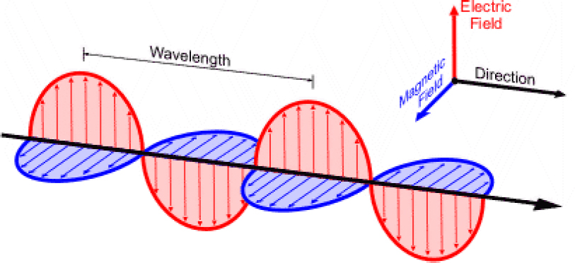
tion in which the wave is traveling (and therefore the direction in which energy is transported by the wave). Note that the electric and magnetic field are always perpendicular to each other and to the direction of propagation. This is true when the wave is propagating in empty space and also when the wave is propagating inside most uniform materials.
Electromagnetic waves move through space at a certain velocity and, therefore, transport energy through space at this velocity. In empty space, the velocity of these waves is approximately c = 300,000,000 m/s. Inside a material like glass or water or human tissue, the velocity is lower and different for different materials. The electric field and the magnetic field each carry half of the total energy of the wave; however, the electric field usually interacts much more strongly with charges (e.g., the electrons in atoms) than does the magnetic field. Numerically, the strength of the magnetic field in free space is given by the strength of the electric field divided by the speed of the wave, B = E/c, which as noted is a rather large number. So, for most purposes, the effects of the magnetic field on materials are small and in many situations (including everything in this report) can be ignored.
One important property of electromagnetic waves is their polarization. In this context, polarization refers to the direction in which the electric field vector points. As mentioned, it must always be perpendicular to the direction of propagation. So, if the wave is propagating horizontally (e.g., northwards), then the electric field vector could oscillate along the orthogonal horizontal axis (east-west), or it could
oscillate vertically (up-down), because those two axes are both perpendicular to the (northward) propagation direction. One refers to these as horizontally or vertically polarized radiation. (Figure C.1 depicts a wave with vertical polarization.) Of course, the electric field vector could also oscillate along an axis that is tilted at an angle, somewhere between up-down and east-west. This can be described as a superposition of the horizontal and vertical cases.
The concept of polarization is important for the measurements discussed in this report, because the detector used in those measurements is polarization-sensitive. This means that, if the detector is oriented to detect vertically polarized radiation, then it is essentially blind to horizontally polarized radiation. A complete characterization of the electromagnetic field at a certain point in space requires knowledge of both the horizontal and vertical field components. Thus, two independent measurements are needed, in general. The L3 advanced imaging technology (AIT) system discussed in this report is designed to emit only vertically polarized radiation. Therefore, the horizontally polarized component should be zero, or nearly zero. In the measurements described in Chapter 6, both co-polarized and cross-polarized measurements have been performed. Here, co-polarized refers to the situation where the detector is oriented so as to detect the primary (i.e., vertical) component of the radiated wave, while cross-polarized refers to the opposite case. As discussed below, these results confirm that the cross-polarized field component is too small to measure, as anticipated.
The most important number that characterizes an electromagnetic wave is its wavelength. As shown in Figure C.1, the wavelength of a wave is the distance between adjacent crests of the oscillatory wave. An alternative (equivalent) characterization is the frequency of the wave, which is related to the amount of time it takes for the wave to propagate a distance equal to one wavelength. To be specific: if an observer sits at one point in space, the period of the wave is the amount of time between when one field maximum passes that point and when the next maximum passes the same point. The period is the inverse of the frequency. Therefore, one can readily relate the frequency of the wave to its wavelength, by a simple relation: f · λ = V, where f is the frequency of the wave (in units of seconds−1 otherwise known as hertz (Hz)), λ is the wavelength (in meters), and V is the velocity of the wave (in meters per second).1 Because the velocity of electromagnetic waves in empty space is a constant, the same for all waves regardless of their wavelength, one finds that the frequency and wavelength of any wave traveling in empty space are very simply related to each other by an inverse relationship: as the frequency gets larger, the wavelength gets smaller in proportion.
An electromagnetic wave may have any value of wavelength, from very small to very large values. The span of electromagnetic waves, as defined by the numerical
___________________
1V is used for any speed and c is normally used for the speed of light.
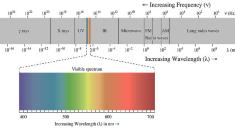
value of their wavelength, is known as the electromagnetic spectrum. It is often illustrated using a logarithmic scale, with shorter wavelengths on one end and longer wavelengths on the other. A typical illustration of the electromagnetic spectrum is shown in Figure C.2.
The different ranges of values for the wavelength (or frequency) are commonly assigned different names: radio waves, microwaves, infrared, and so on. These names are largely based on their historic applications. It is important to realize that there are no well defined, firm boundaries among these different ranges—the names are informal and not rigorously defined. For example, a very-high-frequency microwave at a frequency of 100 GHz (1011 Hertz) might also be called a low-frequency infrared wave. The visible range corresponds to what the human eye can see—these are electromagnetic waves with wavelengths in the range between about 400 and 700 nanometers (1 nanometer = 10−9 meters). For this report, the relevant range is wavelengths of a few millimeters (10−3 meters)—hence, millimeter waves. A wavelength of λ = 10 millimeters corresponds to a frequency of f = 30 GHz. The millimeter wave imaging systems discussed in this report operate at slightly lower frequencies (about 24 to 30 GHz) and, therefore, slightly longer wavelengths (about 24 GHz corresponds to λ ≈ 12.5 mm). Beause there are no well-defined boundaries, when speaking generally, the terms radio frequency (RF), microwave waves, and millimeter waves are often used interchangeably unless explicitly stated.
A second important parameter used to describe the properties of electromag-
netic waves is related to the amount of energy transported by the wave. Colloquially speaking, this is the “strength” of the wave or how much work it can do, and it is a key element in determining whether the wave can cause damage to living tissue. This can be parameterized in several different ways. One way is the power (energy available to do work per unit time) per unit area that is incident on a surface illuminated by the wave in question. This number is known as the intensity (or, the irradiance) of the wave, which is expressed in watts per square meter (W/m2). For example, at sea level, direct sunlight delivers an intensity of approximately 1,400 W/m2—most of which falls in the near ultraviolet, visible, and near infrared ranges.
One may also specify the maximum value of the electric field, E, at a given point. (Note that the electric field oscillates rapidly between its maximum positive and maximum negative values, as shown in Figure C.1, so the average value is zero—but one can still consider the peak maximum value). As noted, this number has units of volts per meter and is directly related to the force exerted on a charged particle by the field. The peak field value is quadratically related to the intensity—thus, doubling the peak electric field corresponds to quadrupling the intensity of the wave. The peak electric field for a wave with a given intensity can be easily computed. For example, for a wave with intensity (I) = 10 W/m2 (which is the same as 1 mW/cm2),
 |
(C.1) |
where c is the velocity of the wave (~3 × 10⁸ m/s), and ε0 is a constant parameter known as the permittivity of free space (given by 8.85 × 10⁻¹² farads per meter). This corresponds to a field of about 87 V/m. Using B = E/c, we can also immediately find that the peak magnetic field is about 0.3 microtesla (1 microtesla = 10−6 T). The value chosen in this example (10 W/m2) corresponds to the maximum permissible exposure (MPE) limit for microwaves and millimeter waves, as specified by several different federal agencies and the Institute of Electrical and Electronics Engineers2 (although this exposure limit also includes a consideration of the duration of the exposure, as discussed in more detail elsewhere in this report).
Lastly, if a wave has a finite size (e.g., if it propagates in the form of a beam), then one may capture the entire wave in a detector and therefore determine the total energy or total energy per unit time (power) carried by the wave. This value is expressed in watts and is simply the sum of the intensity over the entire area covered by the wave. One may also express the total energy using the logarithmic scale known as decibels (dB), referenced to a value of 1 mW (one thousandth of
___________________
2 IEEE, 2005, “IEEE Standard for Safety Levels with Respect to Human Exposure to Radio Frequency Electromagnetic Fields, 3 kHz to 300 GHz,” IEEE Std C95.1™-2005.
a watt). This is abbreviated as dBm: the value 0 dBm corresponds to 100 mW; the value −10 dBm corresponds to 10−1 mW, which is the same as 100 µW. Many of the results described in Chapter 7 of this report show the intensity of a measured radiation field, given in units of decibels (referenced to 1 mW) per square centimeter (dBm/cm2). For example, −40 dBm/cm2 means 10−4 mW (or 100 nW) per square centimeter. The above-mentioned MPE value of 10 W/m2 is equivalent to 0 dBm/cm2. So, a value of −40 dBm/cm2 would correspond to an intensity that is 10,000 times lower than this MPE value.
It is also important to recall that light is not only a wave. Quantum mechanics teaches that light is also a stream of particles known as photons. A photon is the quantum particle of light, carrying a discrete amount of energy, and is indivisible. Thus, in a light wave, the smallest possible energy is that of a single photon. The energy of a photon is directly proportional to the frequency of the light wave and is very small (e.g., a single photon of visible light carries about 10−19 J of energy). Thus, a typical beam of visible light with, say, 1 W of energy, consists of something like 1019 photons per second—a very large number! The quantum (photon) nature of light must be considered only in the case where one is discussing an individual photon or a very small number of photons. In cases where the number of photons is large (as is typically the case), this discreteness can be ignored. This is even more true in the millimeter wave range of the spectrum, where the energy of a single photon is even smaller. For a millimeter wave electromagnetic field of −40 dBm/cm2 at a frequency of 30 GHz, the number of photons per second per square centimeter is about 5 × 10¹⁵—a very large number, even for this exceedingly weak (low-power) field.
THE RADIATION ALL AROUND US: BLACKBODY RADIATION
All normal matter in the universe—that is, everything made of atoms—interacts with electromagnetic radiation. This interaction involves atoms either absorbing energy from the electromagnetic field or emitting energy in the form of electromagnetic radiation. The rates of these various processes depend on the temperature of the matter. As a result of these interactions, all objects emit a characteristic type of electromagnetic radiation, known as blackbody radiation. For any object at a fixed temperature T (expressed in Kelvins), one can compute the power emitted by the object at any particular frequency of interest. Conversely, from a measurement of the spectrum (power versus frequency) of radiation emitted by an object, called the blackbody radiation curve, one can accurately determine the temperature of the object. This theoretical description of the blackbody radiation curve, first described by Max Planck in about 1900, and hence called Planck’s Law, represents a very profound result in the history of physics. The result does not depend on the nature of the object, its composition, or its shape or color—only on its temperature.
Blackbody radiation is typically depicted in a blackbody radiation curve (or a blackbody spectrum) where the peak is inversely proportional to the temperature, as described by Wien’s law. The peak in the blackbody radiation curve from the Sun occurs in the visible part of the electromagnetic spectrum, corresponding to a temperature of about 6,000 K (which is about 5,700°C)—the temperature of the Sun’s surface. An object at room temperature (293 K) has a peak emission of radiation in the infrared region of the spectrum, approximately at a wavelength of 10 µm. Thus, things at room temperature do not “glow in the dark” in the visible range of the spectrum, but they do glow in the infrared, so an infrared camera (i.e., night vision) can be used to see their blackbody emission. Heating up an object causes its blackbody spectrum to shift from the infrared (when it is at room temperature) to the visible region (when it is “red hot”)—which is why hot objects glow visibly.
The relevance of blackbody radiation to this report lies in its use in passive imaging systems. An imaging system that views the blackbody radiation from, for example, a person, can be used to locate hidden objects under the person’s clothing, because the object would likely be at a different temperature from the person and would therefore emit a different spectrum of blackbody radiation, or it would reflect blackbody radiation from the environment that is at a different temperature. This results in a “shadow” of the object in the image of the person. Passive imaging systems that operate in the millimeter or submillimeter range of the spectrum will be discussed in the next appendix of this report.
Additionally, it is instructive to know how much blackbody radiation is present in our everyday environment. Because all objects emit blackbody radiation at all times, we are continuously bathed in this infrared radiation for every moment of our lives. For example, a room temperature black body emits about 1 µW (10−6 W) of power per square meter of area in the relevant millimeter wave range from 24 to 30 GHz. This corresponds to a tiny fraction—about 3 parts in a billion—of the total radiated blackbody power. This is because the blackbody spectrum (for a room-temperature object) peaks in the infrared (near a wavelength of 10 microns, 10−5 m, or 10 µm) and falls off quite rapidly at both longer and shorter wavelengths. In an indoor room-temperature setting, a person receives about 900 W of total power from the blackbody radiation in the environment, more than half of which comes from wavelengths between 5 and 15 microns. For this reason, most passive imaging systems operate in the “thermal” infrared, although there are some examples at longer wavelengths, including in the millimeter wave range. The L3 AIT system, which is the topic of this report, is an active imaging system in which the target is illuminated by an artificial source of radiation, and which therefore does not make use of blackbody radiation. Its design is not sensitive enough to detect blackbody radiation in the 24 to 30 GHz range of operation.
ELECTROMAGNETIC WAVES INTERACTION WITH MATTER: BEAM ATTENUATION AND ENERGY DEPOSITION
In considering the health implications of exposure to electromagnetic waves, one must consider the interaction between the waves and the material with which it is interacting. The details of the interaction depend on both the properties of the wave (i.e., its frequency) and the properties of the material in question. For a given frequency, waves will interact with different materials very differently. One must therefore consider the properties of materials that give rise to these differences.
The details of these light-matter interactions are quite complex and require sophisticated calculations to describe in detail. However, some general statements can be made that will be helpful in understanding the hazards associated with exposure to millimeter waves. There are two particular material properties to be considered. One of these is the velocity of the wave inside the material (always less than the velocity of the wave in empty space), which determines the fraction of the wave that is transmitted into the material. The other is the absorption coefficient, which determines the amount of energy deposited by the electromagnetic wave inside a specific mass or volume of material.
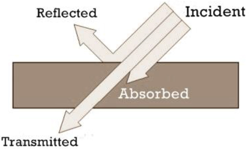
One can envision a wave propagating in empty space and impinging on the surface of a material (called the incident wave). Some of the wave reflects off that interface, and the remainder transmits through the interface into the material. Because the total energy of the wave must remain constant, it is clear that the sum of the transmitted energy and the reflected energy must equal the energy that was contained in the incident wave. The fraction reflected and the fraction transmitted depend on the ratio of the velocity of the wave in the material to its velocity in empty space (because the wave inside the medium is always slower, that ratio is always less than one). The calculation of the reflected and transmitted fractions, known as the Fresnel coefficients, is somewhat complex, but the general behavior is easy to understand. A larger speed mismatch gives rise to a larger reflection. For some materials, the velocity ratio is close to one—in this case, the reflected wave is weak and most of the energy is contained in the transmitted wave. For other materials, that ratio could be smaller, in which case the reflected wave contains more energy and the transmitted wave contains less. One familiar example is the reflection that one sees when one looks in a glass window. About 4 percent of the power in visible light is reflected in a typical window, while 96 percent is transmitted. Therefore, when we look out of a window, we see a weak reflection of ourselves, but mostly a view of the light from outside. In general, the velocity ratio depends on the frequency of the light, which means that the fractions reflected and transmitted also do. However, this dependence is usually fairly weak within the range of frequencies visible to human eyes, so we do not often see materials that exhibit visible color changes as a result of this effect.
This reflection and transmission phenomenon is crucial to the use of millimeter waves for the AITdiscussed in this report. These devices are active imaging systems, which mean that they generate millimeter waves and direct them toward a target to be imaged. The waves partially reflect off of the surface of the target and return to the detectors. That reflected wave is used to form the image, after appropriate signal processing. If there were no reflected wave, then the only way to form an active image would be to use the transmitted wave. However, as we shall now see, this is impossible for imaging living tissue (i.e., people) using millimeter waves.
After the wave has interacted with the air-matter interface, the second important material property is considered, which can have a strong influence on the transmitted fraction of the wave. As this transmitted wave propagates through the material, it can deposit energy in the material through a process known as absorption—that is, the atoms and molecules that compose the material absorb energy from the wave. When this happens, the wave gets weaker because it has lost energy to the material. This energy deposited in the material is the origin of any possible changes to the medium, including any potential health effects, both positive (e.g., aiding in maintaining optimal body temperature) or negative (e.g., local burning).
The strength of a material’s absorption coefficient can vary tremendously, depending on both the frequency of the wave and on the detailed chemical composition of the material. If the absorption is weak, then only a small amount of energy (or maybe none at all) would be deposited in the material, and the wave emerging from the other side would be almost unaltered. Such a material would be described as transparent. In contrast, if the absorption is very strong, then the wave may lose all of its energy to the material. In this case, no wave would emerge from the opposite side of the material. This material would be described as opaque. For example, glass is transparent to visible light, but it strongly absorbs ultraviolet light. If human eyes could see ultraviolet light, then glass windows would look opaque. Most building materials (except for metals) are transparent to frequencies in the range of a few gigahertz, even though they are opaque to human eyes. Thus, cell phones work even when used indoors, because the waves from the phone can propagate out of the building and reach the cell tower. However, at these frequencies, liquid water is a strong absorber, which explains why a microwave oven (operating in the same frequency range) can rapidly heat up a cup of coffee. On the other hand, liquid water is almost completely transparent to visible light, which is why visible light can transmit through human eyes (liquid-filled spheres) to reach the retina (the light-sensing cells at the back of the eye). Evidently, absorption strength can vary dramatically with wavelength. Figure C.3 shows a representation of reflection, transmission, and absorption for a thin slab of material, as discussed above.
As noted, the absorption strength of liquid water is strong at frequencies in the microwave and millimeter wave ranges. Thus, exposure to radiation of this type can lead to the heating of living tissue (which, after all, is mostly water). Obvi-
ously, too much heating can damage tissue and lead to detrimental health effects. Generally, this heating effect is by far the dominant mechanism for transferring energy from millimeter waves to tissue—energy that could lead to health implications for exposure to microwaves and millimeter waves; no other energy transfer mechanisms for the human body have been identified in this region of wavelengths. In contrast, exposure to shorter wavelengths (e.g., ultraviolet radiation or X rays) can have quite different effects. At these shorter wavelengths, one must consider the interaction of an individual photon with individual atoms or molecules that comprise the material in question (e.g., water). This is because the photons that comprise a beam of shorter-wavelength radiation have higher energies (recall that the photon energy is proportional to the frequency and therefore inversely proportional to the wavelength). These higher-energy photons may have sufficient energy to break chemical bonds or induce some other type of chemical reaction (here, a chemical reaction is defined as any process that changes one chemical substance into a different substance, including alterations in molecular structures, so that the entity exhibits significant changes in its properties). If the photons have this much energy, then they can induce photochemical alterations in living tissue, leading to such consequences as sunburn or skin cancer.
It is important to distinguish between the effects of heating (as in boiling a
cup of water in a microwave oven) and other effects that are more likely at higher frequencies (i.e., inducing chemical reactions). The energy of a photon from a wave with a frequency of 30 GHz is more than 20,000 times smaller than the energy of a photon from an ultraviolet wave. This is far too small to induce any type of chemical reaction in any known material. As a result, such interaction mechanisms are highly implausible. This is why, when considering the health and safety implications of exposure to microwaves or millimeter waves, the overriding concern is that of heating.
ANTENNAS AND WAVEGUIDES
The above discussion of the interaction of electromagnetic waves with matter is generally applicable to materials in which all of the electrons are bound to atoms or are participating in chemical bonds and are, therefore, not free to move far from their starting points. However, another class of materials can be distinguished in which some of the electrons are free to move—that is, they are not bound to any atom or chemical bond. These materials are known as conductors, because this characteristic allows them to conduct electricity. Metals such as aluminum, copper, and iron are common examples. The application of a constant (dc) electric field results in a force on the electrons in the conductor, causing them to flow in a particular direction. This net motion or transport of charge is known as electrical current. Of course, current flow in conductors is the basis for most familiar forms of electricity, such as the current supplied by a battery. The electric fields of an electromagnetic wave can also exert forces on charges in a conductor, but these fields are oscillating (ac), not constant (dc). As a result, the charge motion associated with these forces is also oscillatory: when exposed to an oscillating electromagnetic wave, the charges in a conductor will oscillate, sloshing back and forth inside the metal—an ac current. An antenna is a conductor that has been configured to maximize this ac current response to an electromagnetic field of a given frequency. It is also important to note that antennas can also transmit radiation, because oscillating charges always radiate electromagnetic waves. If an oscillating (ac) current is driven in an antenna, then it will radiate electromagnetic waves at the same frequency as the ac current. Antennas are therefore useful for both transmitting and receiving electromagnetic energy.
Antennas may be engineered to respond to fields in many different ways. For example, one can design an antenna to respond to fields that arrive from just one particular direction. This same antenna, if driven by an ac electrical circuit, would radiate in only that one particular direction. Alternatively, an antenna can be designed to be nearly omni-directional, meaning that it receives from (or transmits to) all directions just about equally. The antenna in a cell phone is nearly omni-directional, which explains why a cell phone does not have to be pointed
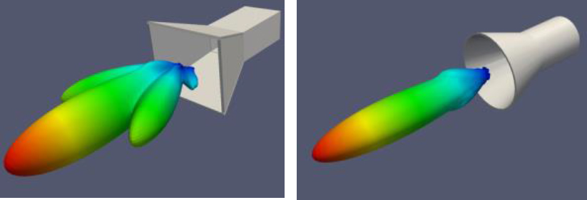
at the nearest cell tower in order to make a phone call. In contrast, parabolic dish antennas are highly directional, transmitting (or receiving) only in the direction in which the dish is facing. A horn antenna is a very directional type of antenna that works well at microwave and millimeter wave frequencies, both as an emitting and a receiving element. Horn antennas are used in the L3 millimeter wave AIT systems to deliver radiation to a very well-defined region of space where the target to be imaged is located. Figure C.4 illustrates two types of horn antenna, along with their calculated radiation patterns. These patterns illustrate graphically the directionality of the emitted radiation—the color scale represents the intensity of the emitted radiation in different directions, going from red, the most intense, to blue, the least intense. Here, the most intense fields are radiated in the forward direction, demonstrating that these horn antennas are highly directional. It should be noted that even though the forward direction is the direction with the highest intensity, the intensity to which an object is exposed, even in the forward direction, decays with increased distance between the object and the horn.
Most antennas produce radiation that is polarized. The polarization of an electromagnetic wave refers to the direction in which the wave’s electric field is pointing. As noted above, the electric field is always oriented perpendicular to the wave’s propagation direction. For a wave propagating horizontally (i.e., parallel to the floor), the electric field could therefore be pointing horizontally (also parallel to the floor but perpendicular to the direction of propagation) or vertically (again, perpendicular to the propagation direction). These two possibilities are referred to as horizontal and vertical polarization, respectively. In the L3 AIT system, the radiation emitted by the system’s horn antennas is vertically polarized. This be-
comes important in measuring the radiation from the system, as the detector (also a horn antenna connected to a waveguide) must be oriented so as to be sensitive to vertical polarization. If it is oriented incorrectly, then the detected signal will not accurately reflect the strength of the electric field incident on the detector. In the testing done as part of this study, measurements of both the vertical and horizontal component of the wave were performed, in order to verify that the horizontal component is essentially zero (i.e., too small to measure), thus confirming that the wave is indeed vertically polarized. These measurements are discussed in detail in Chapter 6 of this report.
In addition to transmitting and receiving electromagnetic waves, conductive structures can also be used for transporting electromagnetic energy from one place to another. The most familiar example is that of a simple metal wire. For instance, every appliance has a plug, which transports ac electric currents (and the associated electromagnetic field) from the wall to the appliance. At the very low frequencies used to power most appliances (in the United States, 60 Hz), one need not worry too much about interference between adjacent wires. However, at higher frequencies, such as those used by microwave and millimeter wave devices, interference can be a significant source of concern. In addition, the energy lost to radiation as current flows along a wire can become substantial at these high frequencies. For this reason, it is generally favorable to transport electromagnetic energy in the form of radiation contained in a waveguide, rather than in the form of oscillating electrical current.
A waveguide is any device structured to guide electromagnetic waves from point to point with minimal loss of energy (and therefore also minimal interference from other sources of energy). In the optical region, a familiar example of a waveguide is an optical fiber, a narrow tube of glass that can guide optical signals over distances of kilometers with very low loss. At lower frequencies, in the millimeter wave and microwave ranges, coaxial cables and small metal pipes are most commonly used. These are conductors that have been carefully designed in a configuration to maximize the transmission of electromagnetic radiation of a given frequency (or a given range of frequencies). Such waveguides are employed in the L3 millimeter wave AIT system to transport the millimeter wave radiation from the source (where it is generated) to the horn antennas (where it is radiated into free space). It is important to understand that these waveguides are highly engineered and optimized with the goal of minimizing the losses, so that the largest possible fraction of the input power can reach the output end. Nevertheless, waveguides are not perfect, so there is some unavoidable amount of energy loss associated with this transport process. As a result, the amount of energy generated at the source is always greater than the amount of energy supplied to the horn antenna. For example, in the L3 system, the energy delivered to each horn antenna is more than 100 times smaller
than the energy generated by the electronic amplifier used as the source. This energy loss cannot be avoided and must be accounted for in the system design to guarantee that the signals emitted from the horn antenna are large enough to be useful in image formation.


