
Suggested Citation:"Appendix E: L-3 Failure Modes and Effects Analysis Document." National Academies of Sciences, Engineering, and Medicine. 2017. Airport Passenger Screening Using Millimeter Wave Machines: Compliance with Guidelines. Washington, DC: The National Academies Press. doi: 10.17226/24936.
×
E
L-3 Failure Modes and Effects Analysis Document
The L3 Failure Modes and Effects Analysis document is reprinted in this appendix.
Suggested Citation:"Appendix E: L-3 Failure Modes and Effects Analysis Document." National Academies of Sciences, Engineering, and Medicine. 2017. Airport Passenger Screening Using Millimeter Wave Machines: Compliance with Guidelines. Washington, DC: The National Academies Press. doi: 10.17226/24936.
×
TABLE E.1
| Component | Device Detail | Failure Mode | System Effects |
|---|---|---|---|
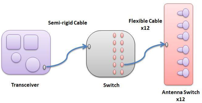
| Assembled transmitter source, switching matrix and antenna elements. | Each antenna mast includes a single transceiver. Mast RF path block diagram is the same for the all ProVision systems | Failures on the antenna mast will be at the component level as detailed in the list below | |
| Transceiver | Output power amplfier, This is the last amplification stage in the TX path. | Amplifer integrated circuit failure | Reduced TX output power on all antenna elements detectable degradation in system self test. |
| Transceiver | Output amplifier input source | Overdrive of RF input into transceiver output amplifier | TX output power would not increase above the normal operating level for the system. |
| Transceiver | Output amplifier input source | Pulse modulator control circuit malfunctions. | Peak TX output power level would be the same as in normal operation. |
| Transceiver to manifold cable | Semi-rigid coaxial cable. | Mechanical damage to cable | Reduced TX output on all antenna elements, detectable degradation in system self test. |
| Manifold Switch | Connectorized switch module. MMIC switch components are the only active devices in the signal path. | Switch integrated circuit failure | Reduced TX output on one or more antenna modules, detectable degradation in system self test. |
| Manifold Switch | Input coaxial cable | Compromised connection on coax input cable from the transceiver. | Reduced output power on all manifold ports and corresponding down stream antenna ports, detectable degradation in system self test. |
| Manifold Switch | Power and control cable to manifold switch | Compromised connection of power and control signal ribbon cable. | Significantly reduced TX output, detectable degradation in system self test. |
| Manifold Switch | Manifold switch control circuitry | Damaged control circuit | Reduced TX output on many antenna ports, detectable degradation in system self test. |
| Manifold Switch | Output port coaxial connector | Compromised connection on the output port coax connector. | Reduced TX output to one of the antenna modules, detectable degradation in system self test. |
Suggested Citation:"Appendix E: L-3 Failure Modes and Effects Analysis Document." National Academies of Sciences, Engineering, and Medicine. 2017. Airport Passenger Screening Using Millimeter Wave Machines: Compliance with Guidelines. Washington, DC: The National Academies Press. doi: 10.17226/24936.
×
| Component | Device Detail | Failure Mode | System Effects |
|---|---|---|---|
| Flexible cable manifold to antenna | Flexible coaxial cable. | Mechanical damage to cable | Reduced TX output on a single antenna module, detectable degradation in system self test. |
| Antenna module | Custom module with coax input and integrated antenna element outputs. GaAs MMIC switch components are the only active devices in the signal path. | Switch integrated circuit failure | Reduced TX output on one or more antenna elements, detectable degradation in system self test. |
| Antenna module | Input port coaxial connector | Compromised connection on input signal coax connector. | Reduced TX output to all antenna elements on the module, detectable degradation in system self test. |
| Antenna module | Power and control cable to manifold switch | Compromised connection of power and control signal ribbon cable. | Greatly reduced TX output, detectable degradation in system self test. |
| Antenna module | Antenna switch control circuitry | Damaged control circuit | No TX output on many antenna ports, detectable degradation in system self test. |
| Antenna module | Antenna element | Compromised antenna feed structure | RF output degradation on a single element, detectable degradation in system self test. |
NOTE: GaAs, gallium arsenide; MMIC, monolithic microwave integrated circuit; RF, radio frequency; TX, transmitter.
Suggested Citation:"Appendix E: L-3 Failure Modes and Effects Analysis Document." National Academies of Sciences, Engineering, and Medicine. 2017. Airport Passenger Screening Using Millimeter Wave Machines: Compliance with Guidelines. Washington, DC: The National Academies Press. doi: 10.17226/24936.
×

