
J
Bolting Preload
This appendix presents background information regarding bolting preload and safety factors used in bolting design.
BOLTING PRELOAD
During assembly in the OEM shop, the BOP/LRMP stack is “built up” by placing one RAM on top of another and bolting them together at the flanges. A ring gasket is placed between the flange faces and bolts (or studs and nuts) are tightened. The procedure for tightening flange bolts must conform to various industry and OEM specifications to ensure bolts are tightened as evenly as possible.1,2 Flange bolting procedures include the following:
- A criss-cross bolt tightening pattern,
- A bolt tightening sequence (e.g., all bolts are hand tightened, then all bolts are tightened to 25 percent of desired preload, then 50 percent, then 75 percent, then 100 percent);
- Determination of required bolt preloading, as discussed below; and
- Method of achieving and verifying bolt preload, also discussed below.
___________________
1 API Engineering bulletin EB 962D, March 29, 2016.
2 John H. Bickford, “An Introduction to the Design and Behavior of Bolted Joints;” Third Edition, Revised and Expanded, John H. Bickford, Marcel Dekker, Inc., 1995.
Drilling rig contractors use the same technique when maintaining a BOP stack is on the deck of the rig. Industry also has the ability to tightening bolts and nuts when the BOP stack is deployed underwater using a remotely operated vehicle (ROV).
Determining Bolt Preload
The tensile preload for closure bolting must provide sufficient clamping force between flanges, seal rings, or component faces so that they remain sealed when flange connectors are subjected to service loading conditions.
API Spec 17D specifies the following tensile preloading of flange bolts:
- All 6BX and 17SS (types of API flanges) flange bolts be preloaded to between 67 percent and 73 percent of a bolt’s yield stress.3
- A maximum allowable tensile loading on flange bolts, including forces from rated internal pressure, based on the root area of the thread, of 83 percent of yield strength (through API Spec 6A and ISO 10432).4
Thus, the bolt preload alone makes these bolts highly loaded, with little room for additional loading despite the fact that additional tensile loads on the bolts are minimal until the flange preload is exceeded.
The flange bolt installation is a process that is critical to flange performance and integrity. This is particularly true for achieving the required tensile preload on a flange bolt. API Spec 17D, Section 7.5.5 merely recommends the following regarding bolting makeup torque,5
The use of calibrated torque or bolt-tensioning equipment is recommended to ensure accurate make-up tension.
Bolt Preloading Technique
There are many methods that can be used to impose the required fastener preload. These include the following:
- Application of a controlled torque to the threaded fastener, the method currently specified in the API standards. Applicable friction coefficients are generally not known, but approximations based on a consideration of the
___________________
3 API Specification 17D, ISO 1 3628-4, 2nd Edition, May 2011, Section 5.1.3.5, p. 19.
4 API Specification 17D, 1st Edition, August 1, 1996, Section 303.4, p. 22.
5 API Specification 17D, ISO 13628-4, 2nd Edition, May 2011, Section 7.5.5, p. 66.
- surface characteristics, type of lubrication, and type of or coating have been made. Torque is applied with a torque wrench or an alternate energy source. The types of available torque wrenches include mechanical (i.e. force applied to a lever arm), electrical, pneumatic, and hydraulic. Selection of the type of torque application system to be used depends on the required torque level and specific application (e.g., above or below water).6,7,8,9 Torque has been shown to be an inaccurate metric for assuring actual bolt preload.10,11
-
The RCSC technique was developed by the Research Council on Structural Connections (RCSC). This technique is a variant of the torqueing technique with many quality control enhancements. Although the RCSC technique references ASTM standards rather than API specifications, and was developed for bolted structural connections on bridges and buildings, it may have some applicability to flange connectors. Some interesting aspects of the RCSC technique are
- It addresses both LRFD (probabilistic) design and allowable strength (safety-factor) design.
- It addresses protected storage requirements for bolts.
- It only addresses bolts with diameters up to 1½ in.
- It requires and engineer-of-record who is responsible for designing the joint and for proper bolting in the field.
- It addresses bolt fatigue.
- It requires the use of a tension calibrator to determine the “nut factor” for each manufacturing lot of bolts, studs, and nuts. The “nut factor” is an unknown variable when determining the proper torque to apply for a desired preload. The engineer-of-record must witness every tension calibration test to ensure the proper “nut factor” is used in the field.
- It requires an inspector in the field to ensure the proper torque is applied to each bolt.
- It requires daily calibration of wrenches used in bolt tightening.
- Pre-tensioning is the technique of using hydraulic pistons attached directly to the end of the fasteners. Once the desired tensile load is imparted, a restraining nut is attached preserve the length of the stretched bolt. The
___________________
6 J.E. Shigley, Mechanical Engineering Design, McGraw-Hill, New York, 1972, pp. 291-320.
7 Tentec, “Tensioners,” http://www.tentec.net/tensioners.php, accessed May 2017.
8 Atlas Copco, “Bolt Tightening Solutions,” http://www.atlascopco.co.uk/en-uk/itba/products/Bolt-tightening-solutions, accessed May 2017.
9 Torq/Lite, “Hydraulic Torque Wrenches,” http://www.torqlite.com/, accessed May 2017.
10 K.H. Brown, C. Morrow, S. Durbin, and A. Baca, Guideline for Bolted Joint Design and Analysis: Version 1.0, SAND2008-0371, Sandia National Laboratories, Albuquerque, N.M., January 2008.
11 Lester Burgess, discussions with Nancy Cooke and Bill Capdevielle, May 31, 2017, presented to the committee on August 28, 2017.
- imposed tensioning force can be measured directly with an integral load cell, or it can be calculated from the imposed pressure and pressure-bearing area of the piston. One subsea equipment company uses pre-tensioning exclusively.12
- As an additional check, after connector installation with either a torque wrench or a direct tensioning system, the resulting stretch in the bolt can be measured by a variety of techniques including mechanically (e.g., with a set of calipers if access to both ends is available) or ultrasonically.13 With knowledge of an appropriate spring constant for the connector, then the imposed force can be calculated if the length of the fastener under tensile load is known.
Estimates for the uncertainty range of effective bolt tensile loading when exact torque is applied is on the range of ±25 to 30 percent.14,15,16 Uncertainty in the application of torque on fasteners is caused by several factors, some of which aren’t controlled by standards and specs. Examples are the effect of thread manufacturing tolerances and friction factor (nut factor) to be used for particular lubricants and coatings.17
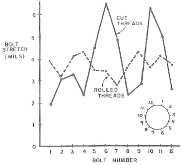
There are also some indications that the thread manufacturing technique influences bolt preload accuracy and variability. Figure J.1 shows the how the residual preload (as indicated by bolt stretch) can vary for cut threads and for rolled threads after a two-pass bolt-up procedure.18
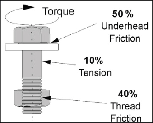
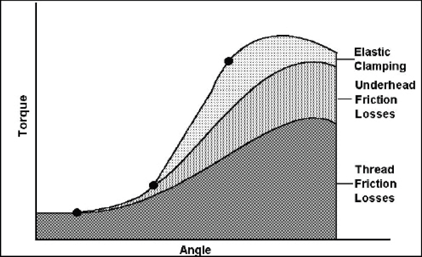
Schoberg estimated the efficiency of using torque to generate bolt tension.19 As shown in Figures J.2 and J.3, estimated that 10 percent of the applied torque resulted in elastic preloading of a bolt that clamps components together. He further
___________________
12 Bill Capdevielle, discussions with ITH Engineering at the 2017 Offshore Technology Conference, Houston, Tex.
13 Boltight Limited, “Introduction to Ultrasonic Bolt Load Measurement,” http://www.boltight.com/products/echometer.html, accessed May 2017.
14 K.H. Brown, C. Morrow, S. Durbin, and A. Baca, Guideline for Bolted Joint Design and Analysis: Version 1.0, SAND2008-0371, Sandia National Laboratories, Albuquerque, N.M., January 2008.
15 Lester Burgess, discussions with Nancy Cooke and Bill Capdevielle, May 31, 2017, presented to the committee on August 28, 2017
16 J.H. Bickford, An Introduction to the Design and Behavior of Bolted Joints, Third Edition, Marcel Dekker, Inc., New York, N.Y., 1995.
17 R.S. Shoberg, PE, “Engineering Fundamentals of Threaded Fastener Design and Analysis,” PCB Load and Torque, Inc., Farmington Hills, Mich.
18 J.H. Bickford and M.E. Looram, Good Bolting Practices, A Reference Manual for Nuclear Power Plant Maintenance Personnel, Volume 1: Large Bolt Manual, Electric Power Research Institute, Palo Alto, Calif., 1987.
19 R.S. Shoberg, PE, “Engineering Fundamentals of Threaded Fastener Design and Analysis,” PCB Load and Torque, Inc., http://www.hexagon.de/rs/engineering%20fundamentals.pdf.
estimated that 50 percent of the torque was consumed by underhead friction and 40 percent of the torque is consumed by thread friction. He concludes that, “an increase in either friction component of 5 percent can reduce pre-load tension by half.”20
Safety Factors for Flange Bolts
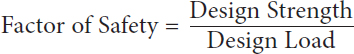
The maximum allowable design loads for flange bolts is decreased by a factor of safety. “Factor of safety (FoS), also known as safety factor (SF), is a term describing the structural capacity of a system beyond the expected loads or actual loads. Essentially, how much stronger the system is than it usually needs to be for an
___________________
20 Ibid, p. 5.
intended load.”21 The purpose of a safety factor is to accommodate any variations or uncertainties regarding actual loads and bolt properties.22 The safety factor is determined by the following equation:23
Design Strength can be defined in several ways, but two commonly used are:
- Nominal ultimate tensile strength, which is the stress at which the bolt’s material would be expected to fail by breaking or fracturing based on the load and original cross-sectional area; and
- Yield strength, which is the stress which will cause the bolt to plastically deform, usually defined as nominal 0.2 percent strain from its original length.
The traditional factor of safety is based on ultimate tensile strength. However, on ductile metals in a pressure connection it is not inappropriate to check the factor of safety on both ultimate tensile strength and yield,24 since a flange connection whose bolts yield enough can fail to maintain pressure boundary, even if they have not fractured. As discussed later in this appendix there does not appear to be any industry practice to examine bolts for plastic deformation unless they have deformed enough to leak, or fractured entirely.
API Specification 17D, “Specification for Subsea Wellhead and Christmas Tree Equipment,” specifies bolt loading limits as a percentage of yield stress (not ultimate tensile strength), because plastic deformation of bolts is as undesirable an event as an actual bolt failure if it leads to failure of the connector to maintain the pressure boundary of the well.
A similar design parameter is the margin of safety (MoS),25 sometimes referred to as the safety margin. The margin of safety describes “ratio of the strength of the structure to the requirements.” The margin of safety can be calculated by the following equation:26
___________________
21 Mechanical 360, “Factor of Safety and Margin of Safety,” https://www.mechanical360.net/updates/factor-of-safety-and-margin-of-safety, accessed November 10, 2017.
22 E.A. Avallone, T. Baumheister III, and A.M. Sadegh, Marks Standard Handbook for Mechanical Engineers, 11th edition, McGraw-Hill, New York, N.Y., 2007.
23 Mechanical 360, “Factor of Safety and Margin of Safety,” https://www.mechanical360.net/updates/factor-of-safety-and-margin-of-safety, accessed November 10, 2017.
24 Ibid.
25 Ibid.
26 Ibid.
or
Margin of Safety = Factor of Safety – 1
Similarly, a yield margin of safety could be defined substituting the yield load for the failure load.
The yield margin of safety for flange bolts can be derived from the working stress limitations specified in API Spec 17D, which recommends the following:
- For bolt preload (the initial “tightening of a flange bolt to achieve flange face closure force), the bolt should be placed in a tensile loading state of 67 to 73 percent of maximum yield stress.27
- For bolt in-service loading (the bold preload plus any additional working loads such as pressure, externally-applied tension, or bending moments on the connector) the tensile loading on the bolt shall not exceed 83 percent of maximum yield stress.28 This equates to a yield margin of safety of .205.
It is useful to compare the safety margins for subsea wellhead and Christmas tree equipment, as specified in API Spec 17D, to the safety margins for surface wellhead and Christmas tree equipment, as specified in API Spec 6A.29 For surface wellheads bolt preloading is specified at only 50 percent of yield; the operational bolt loading remains at 83 percent of yield.
Consider that the operational loading on the onshore Christmas tree bolts would be mainly from internal pressure on the connector, which is known to a high degree of certainty. Piping support systems would virtually eliminate any external loads on the connectors such as tension or bending moments. Additionally, the flange bolts themselves are not exposed to the potentially corrosive underwater environments (including cathodic protection) as the subsea flanges being considered in this study report.
Subsea wellhead and Christmas tree bolts suffer additional and greater integrity risks, including:
___________________
27 API Specification 17D, ISO 1 3628-4, 2nd Edition, May 2011, Section 5.1.3.5, p. 19.
28 API Specification 6A, ISO 10423:2009 (Modified), 20th Edition, October 2010, Section 4.3.4, p. 28.
29 API Specification 6A, ISO 10423:2009 (Modified), 20th Edition, October 2010, Section 4.3.4, p. 28.
- Service in high-pressure salt water—sometimes hypersaline
- Exposure to H2S, CO2, hydrogen, and cathodic protection
- Potential tensile forces coming from the rig through the riser
- Potential bending moments caused by deep water currents
The above four factors place significant and often uncertain environmental stress and loading on subsea bolts.
Perhaps the most critical factor in considering the appropriateness of the safety factors implied by API RP 17D is the accuracy of the bolt preloading technique—for both surface and subsea applications. As discussed above in the section on Bolt Preloading, torqueing is a very inaccurate method for achieving bolt preload. The ±25 to 30 percent accuracy range of using torque to preload bolts and nuts should be considered when determining the suitability of 20.5 to 50 percent (preload and operating) safety margins. It is problematic to consume 50 to 60 percent of a very narrow bolt preload safety margin with preload variability. This margin should be set accounting for uncertainty.


