
3
Nuclear Electric Propulsion
SYSTEM CONCEPT
Nuclear electric propulsion (NEP) systems convert heat from the fission reactor to electrical power, much like nuclear power plants on Earth. This electrical power is then used to produce thrust through the acceleration of an ionized propellant.
An NEP system can be defined in terms of six subsystems, which are depicted in Figure 3.1 and briefly described below.
- Reactor. As with a nuclear thermal propulsion (NTP) system, the reactor subsystem produces thermal energy. In an NEP system, this thermal energy is transported from the reactor to the power conversion subsystem through a fluid loop.
- Shield. As with an NTP system, the shield subsystem reduces the exposure of people and materials in the vicinity of the reactor to radiation produced by the reactor.
- Power conversion. The power conversion subsystem converts some of the thermal energy transported from the reactor to electrical energy through either dynamic mechanical or static solid-state processes, such as flowing a heated fluid through turbines as in terrestrial power plants, or through use of semiconductor or plasma diodes to move charged particles through a material. The remaining thermal energy is rejected as waste heat.
- Heat rejection. Terrestrial power systems can use ambient water and air for convective cooling. The thermal energy created by NTP systems is transferred to the cryogenic propellant and exhausted into space. High-power NEP systems require heat rejection radiators with large surface areas to provide adequate cooling, and, as power levels increase, the size and mass of the heat rejection subsystem has the potential to dominate over other subsystems. Heat rejection at high temperatures reduces the radiator area since radiation increases proportionally to the fourth power of the absolute temperature of the radiator.1 High-temperature operation thereby increases performance, but it becomes a challenge for other aspects of the system.
- Power management and distribution (PMAD). Electrical power from the power conversion subsystem is often generated near the reactor to avoid thermal losses; however, the power must be controlled and
___________________
1 Mission length also impacts radiator area. For longer missions’ larger radiators are required to account for possible damage from micrometeorites.
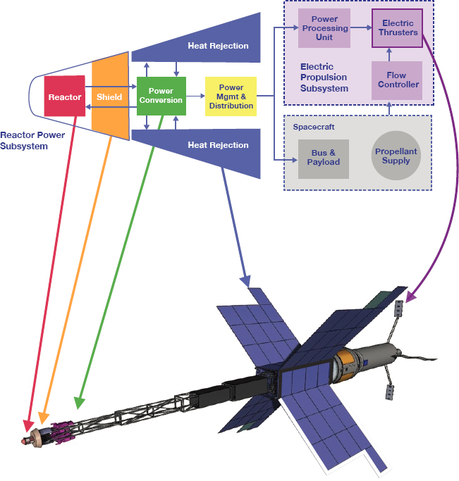
- distributed over relatively large distances to the electric propulsion (EP) subsystems. The PMAD subsystem consists of the electronics, switching, and cabling to manage the electrical voltage, current, and frequency of the transfer efficiently.
- EP. The EP subsystem converts electricity from the PMAD subsystem into thrust through electrostatic or electromagnetic forces acting on an ionized propellant. The EP subsystem consists of the power processing unit (PPU), propellant management system (PMS), and thrusters. The PPU converts the power provided by the PMAD to a form that can be used to generate and accelerate a plasma. A “direct-drive” system would directly drive the EP subsystem from the PMAD subsystem with a commensurate reduction in PPU mass. Power control hardware for switching and power quality would still be required for starting, throttling,
- and managing transients and faults within the EP subsystem. The PMS manages the propellant flow to the thrusters.
NEP system performance is governed by the total system mass required to produce the required power level (i.e., the system specific mass, in kilograms per kilowatt-electric [kg/kWe]), the performance of the EP subsystem, and the lifetime and reliability of all subsystems. System design trades focus on maximizing the power conversion subsystem efficiency, the waste heat rejection temperature, and the efficiency and specific impulse (Isp) of the EP subsystem while achieving the mission lifetime and reliability requirements.
HISTORICAL OVERVIEW
Several U.S. NEP programs have been pursued since the late 1950s, including the following:
- Systems for Nuclear Auxiliary Power (SNAP),
- SP-100 space power reactor,
- Space Exploration Initiative, and
- Jupiter Icy Moons Orbiter (JIMO)/Prometheus.
The SNAP program advanced key NEP technologies from 1958 to 1972. Systems with electrical power output from 0.5 kilowatt-electric (kWe) (SNAP-10A) to 350 kWe (SNAP-50) were developed, using various energy conversion technologies. The reactors were designed to use highly enriched uranium (HEU). Over the course of the program, reactor outlet temperatures increased from 810 K to about 1350 K. The SNAP-10A nuclear reactor is the only one that the United States has launched into Earth orbit. It operated at a power level of approximately 0.5 kWe for 43 days before it was shut down because of the failure of a nonnuclear component. An equivalent reactor was ground tested for more than 10,000 h.
SP-100 was a joint program by NASA, the Department of Defense (DoD), and the Department of Energy (DOE). It was initiated in 1983 with the goal of developing a system that would generate 100 kWe using thermoelectric or thermionic power conversion, with growth potential (using dynamic energy conversion technology) to about 1 megawatt electric (MWe). The reactor was designed to use HEU and produce a reactor outlet temperature of about 1350 K. Substantial advances were achieved for the fuel elements (fuel and fuel cladding), materials (for control rods, reflectors, and shielding), and thermoelectric technologies. Solutions to other technology challenges, however, were still under development when the program was terminated in 1994 as mission and power needs within the multiple sponsoring agencies changed.
The Space Exploration Initiative, which lasted from 1991 to 1993, was intended to develop an NEP system for an opposition-class human mission to Mars with a transit time of 1 year. A reference system was defined at 10 MWe. The program supported research and analysis of 1 to 3 MWe ion and magnetoplasmadynamic (MPD) thrusters before NASA terminated this program without the completion of substantive testing or technology advancement.
The JIMO/Prometheus program, initiated by NASA and DOE in 2003, was intended to develop an NEP spacecraft to explore Jupiter and several of its moons. The NEP system was designed to produce 200 kWe.2 Design advancements were made in dynamic energy conversion, heat rejection, and associated EP technologies. Unfortunately, no relevant-scale component, subsystem, or system testing was performed before NASA terminated the program in 2005 after reevaluating its budgetary priorities.
NASA supported research to advance thruster technologies relevant to megawatt electric power levels in parallel with the above programs, including the 200 kWe mercury ion thruster tested in 1968; fundamental research on 1 to 10 MWe pulsed MPD and pulsed inductive thrusters; 250 kWe steady-state MPD thrusters; and 100 kWe Hall, radiowave-driven magnetized electrothermal (VASIMR®),3 and field reversed configuration thruster concepts
___________________
2 S.S. Voss, “Nuclear Security Considerations for Space Nuclear Power: A Review of Past Programs with Recommendations for Future Criteria,” Nuclear Technology 206:8: 1097-1108, 2020, https://doi.org/10.1080/00295450.2019.1706378.
3 VAriable Specific Impulse Magnetoplasma Rocket.
in the recently completed Next Space Technologies for Exploration Partnerships (NextSTEP) Advanced Electric Propulsion program.4
The most noteworthy non-U.S. space nuclear programs were conducted by the Soviet Union. As noted in Chapter 2, two Thermionic Operating Reactor Active Zone (TOPAZ) I reactors were launched as flight demonstrations, and in the early 1990s the United States purchased a developmental TOPAZ II reactor for nonnuclear test and evaluation.5,6
STATE OF THE ART
This section discusses the state of the art of the subsystem technologies that make up an NEP system as well as associated modeling and simulation (M&S) capabilities.
Integrated MWe-Class NEP Systems
An integrated technology development program aimed specifically toward an NEP system operating at more than 1 MWe has not been undertaken. Although preliminary design studies for MWe-class NEP systems have been conducted, there have not been any significant detailed design, hardware development, or M&S advances for the full, integrated NEP system. NEP technologies, designs, and M&S tools related to HEU fuels, power conversion, heat rejection, and thrusters have been developed for 100 to 200 kWe NEP systems; some of these technologies could be scaled to the megawatt electric power level. Developing an NEP system for the baseline mission will likely involve the use of multiple NEP modules which, in the aggregate, will provide the total propulsive power. This would increase system complexity, especially since the NEP system design includes six major subsystems (on each NEP module), and the spacecraft would also need to incorporate a chemical in-space propulsion system.
Reactor
No reactor has been developed that is representative of that needed for NEP applications. Extensive development has occurred for proposed HEU fuels and cladding for NEP reactors, including irradiations up to NEP-relevant lifetime fuel burnup levels for numerous fuel elements.7,8 Almost no work has been done for high-assay, low-enriched uranium (HALEU) NEP fuels. HEU fuels examined include uranium nitride (UN), uranium carbide (UC), and uranium dioxide (UO2) with cladding made of a refractory alloy, such as Nb-1%Zr,9 molybdenum (Mo) alloys, or tantalum (Ta) alloys, that can sustain operating temperatures of approximately 1200 K. Overall, there is a sound technical basis regarding the fuel and cladding temperatures and fuel burnup levels that are needed for NEP fuel systems. However, significant technology recapture activities would be needed to reestablish robust UN or UC fuel fabrication capabilities.10
Likewise, past efforts developed extensive knowledge on the performance of beryllium (Be) and beryllium oxide (BeO) reflector materials, boron carbide (B4C) control rods, and lithium hydride/tungsten (LiH/W) radiation shield materials. Beryllium and BeO reflectors and control rods have been recently manufactured for the Kilopower program. Fabrication technologies for B4C and LiH/W would need to be recaptured due to little activity over
___________________
4 C.L. Moore, E.J. Pencil, R.L. Hardy, K.J. Bollweg, and M. Ching, “NASA’s NextSTEP Advanced Electric Propulsion Activities,” presentation to the AIAA/SAE/ASEE Joint Propulsion Conference, Cincinatti, OH, 2018, https://ntrs.nasa.gov/citations/20180007411.
5 D. Buden, Summary of Space Nuclear Reactor Power Systems (1983-1992), Idaho National Engineering Laboratory, Idaho Falls, ID, 1993, https://www.osti.gov/servlets/purl/10151265.
6 M.S. El-Genk, “Deployment History and Design Considerations for Space Reactor Power Systems,” Acta Astronautica 64(9-10): 833-849, 2009.
7 J.A. Angelo, Jr. and D. Buden, Space Nuclear Power, Orbit Book Company, Malabar, Florida, 1985.
8 R.B. Matthews, R.E. Baars, H.T. Blair, D.P. Butt, R.E. Mason, W.A. Stark, E.K. Storms, and T.C. Wallace, “Fuels for Space Nuclear Power and Propulsion,” pp. 179-220 in A Critical Review of Space Nuclear Power and Propulsion, 1984-1993, American Institute of Physics, New York, 1994.
9 That is, an alloy of niobium with 1 percent by weight of zirconium.
10 UO2 manufacturing capabilities remain current because UO2 is the predominantly used fuel in commercial nuclear power plants.
the past 16 years. M&S tools for power reactors are well developed but require updating to include the selected materials and reactor designs for the NEP system.
As noted above, NEP reactor designs bear more similarity to terrestrial reactor designs than do NTP systems. Hence, many of the neutronic and thermal-hydraulic M&S tools used to evaluate reactor designs for standard terrestrial applications are applicable to NEP analysis. In the Prometheus program, simulation of reactor and plant interactions were used to determine overall stability of the system.11 The modeling tools used for those simulations may be useful for development of an NEP system for the baseline mission.
Shielding
Space reactor shielding has been analyzed and designed for a range of power levels, and M&S tools used to evaluate radiation transport and thermal management in shielding materials are available. To minimize mass, the shield for an NEP system is designed using a “shadow shield” approach, taking the form of a conical or cylindrical barrier that attenuates radiation in a conical region extending behind the shield, within which the spacecraft and payload are located. For any spacecraft with a source of nuclear radiation, the dose rate is managed by a combination of (1) distance between the reactor (or other source) and the payload and (2) attenuation by the shield. State-of-the-art shielding materials include (1) Be, LiH, and B4C to moderate and absorb neutrons and (2) W to attenuate gamma rays; these were tested in the SP100 program and were planned for use in the Prometheus system as well. Shielding designs incorporated cooling of the LiH, and designs allowed passage of coolant and control lines without radiation leakage. Shield modeling performed in the Prometheus program was deemed mature enough for design, and it was used to verify that coolant and electrical paths could successfully be integrated into the shadow shield.12
Power Conversion
Power conversion technologies relevant to space power systems have been identified in a myriad of system studies and development programs at a range of power levels over decades. The most relevant power conversion technologies are as follows:
- Static
- Thermoelectric converters
- Thermionic converters13
- Dynamic
- Brayton cycle engines
- Rankine cycle engines
- Stirling cycle engines
The level of development and the potential performance of these technologies varies widely, and none have been tested to the power levels required for a MWe-class NEP system in an appropriate operating environment, even if multiple power conversion units are used to meet total power and system reliability requirements.
Thermoelectric converters have a long history in space nuclear fission systems, particularly with the SNAP program and the SP-100 program. Thermionic converters integrated with the reactor core were also used in the
___________________
11 J. Ashcroft and C. Eshelman, Summary of NR Program Prometheus Efforts, Report LM-05K188, 2006, https://doi.org/10.2172/881290.
12 J. Ashcroft and C. Eshelman, Summary of NR Program Prometheus Efforts, Report LM-05K188, 2006, https://doi.org/10.2172/881290.
13 Thermionic converters are static devices that convert heat directly into electricity. They operate at high temperatures with the potential for low specific mass. In their most elementary form, thermionic converters consist of two metal electrodes separated by a narrow gap. One of the electrodes, called the emitter, is held at a high temperature, typically 1800 to 2000 K. The other electrode, called the collector, is held at a lower temperature, typically 900 to 1000 K. The emitter emits electrons into the gap and the lower temperature collector absorbs them. The electrons absorbed by the collector produce a usable electrical current as they return to the emitter through an external circuit. (National Research Council, Thermionics Quo Vadis?: An Assessment of the DTRA’s Advanced Thermionics Research and Development Program, The National Academies Press, Washington, D.C., 2005, p. 15, https://doi.org/10.17226/10254.)
Soviet TOPAZ reactors. Thermoelectric and thermionic converters, however, do not scale well to megawatt electric power levels. As noted above, the SP-100 program would have shifted from static to dynamic power conversion technology to achieve MWe-class performance.
Extensive M&S capability exists for Rankine based power conversion systems used in terrestrial reactors,14 and Brayton cycle models are advanced for some terrestrial applications, but these would require significant upgrades for application to MWe NEP systems.
Brayton power conversion has had the greatest development effort, with NEP relevant development conducted most recently for the Prometheus and Fission Surface Power (FSP) programs, both of which use superalloys, unlike the SNAP-50 system that relied on refractory materials.15 A design schematic for the 200 kWe Prometheus system design is shown in Figure 3.2. The Prometheus project development yielded a test of a state-of-the-art 2 kWe Brayton power conversion system directly coupled to a 2.3 kWe ion thruster to simulate NEP operation. The Brayton system was operated for 800 h.
The Thermionic Fuel Element (TFE) Verification Program focused on life testing of single fuel elements, each with multiple thermionic converters surrounding a UO2 fuel element in a relevant thermal and neutronic environment.16 Prior to the end of the program in 1993, a single fuel element was operated up to 18 months. The TFE, however, required fuel temperatures on the order of 1800 K, which introduced additional structural material concerns for the reactor.17
The characteristics of the most recent power conversion technology tests relevant to space power systems are shown in Table 3.1. As shown, the demonstrated power levels for the different options vary widely, as they were not intended for use in high power, low specific mass systems. The Rankine cycle concept has been tested at 150 kWe. The other three concepts have been tested at power levels that are far below the level needed for a MWe-class NEP

___________________
14 S.A. Wright, R.J. Lipinski, M.E. Vernon, and T. Sanchez, Closed Brayton Cycle Power Conversion Systems: Modeling, Operations and Validation, Sandia National Laboratories, Sandia Report SAND2006-2518, 2006, https://doi.org/10.2172/1177051.
15 A superalloy is a metal alloy with the ability to operate at temperatures up to about 1700 K. Refractory materials, which can operate at even higher temperatures, may be either metal alloys or ceramics.
16 Battelle Energy Alliance, Atomic Power in Space II: A History of Space Nuclear Power and Propulsion in the United States, LLCINL/EXT-15-34409, Idaho Falls, ID, 2015.
17 L. Mason, “Power Technology Options for Nuclear Electric Propulsion,” in Proceedings of IECEC 2002: the 37th Intersociety Energy Conversion Engineering Conference, pp. 114-121, Washington, DC, 2002, https://ieeexplore.ieee.org/stamp/stamp.jsp?arnumber=1391989.
TABLE 3.1 Summary of Nuclear Electric Propulsion-Relevant Power Conversion Technology Tests
| Concept | Power Converter (kWe) | Reactor Exit Temperature (K) | Efficiency (%) | Materials | Program Name and Date |
|---|---|---|---|---|---|
| Thermoelectric | 1.5 | 1300 | 4.2 | Refractory | SP-100 (1993) |
| Thermionic | 0.7 | 1800 | 9 | Refractory | TFEVP (1993) |
| Brayton | 12 | 1150 | 20 | Superalloy | Prometheus (2005) |
| Stirling | 12 | 843 | 27 | Superalloy | FSP (2015) |
| Rankine | 150 | 1100 | 14 | Refractory | SNAP-50 (1965) |
NOTE: FSP, Fission Surface Power; TFEVP, Thermionic Fuel Element Verification Program; SNAP, Systems for Nuclear Auxiliary Power.
system. The tested values for maximum temperatures, power per converter, and the assumed materials to be used are described. The state of the art shown is for actual tested components. Much of the power conversion subsystem estimates used in projections for MWe NEP systems are based on designing existing concepts for operation at higher temperatures and scaling them to higher powers. Scaling to higher power is required, rather than simply using greater numbers of existing components to keep NEP system complexity manageable.
Heat Rejection
Different power conversion technologies have different waste heat rejection needs. Brayton and Stirling power conversion subsystems, which use gaseous working fluids, reject heat over a range of temperatures as the gases cool while passing through a heat exchanger. A Rankine system uses the energy released by a reactor to boil a working fluid, which is subsequently condensed at a constant temperature (the boiling point of the working fluid). Thermoelectric and thermionic converters are cooled either by (1) radiation from the cold side of the converter or (2) a coolant that transfers waste heat to a radiator. Radiator operating temperature and size is determined by various system design considerations.
The transport of heat from the power conversion subsystem to the radiator is generally done either by (1) coolant that is pumped through an array of pipes attached to radiator panels or (2) heat pipes, which are essentially self-contained heat transfer systems that create high thermal conductivity through an internal phase change flow in each heat pipe.
Because a significant portion of the reactor power is rejected as waste heat, radiator panel area and mass can dominate an NEP system. No M&S efforts have focused on the large-scale heat rejection subsystems required for MWe-class NEP systems. In addition, the structural considerations for launch and deployment as well as the large-scale heat pipes required will present significant challenges. The state of the art for NEP-relevant heat rejection subsystems is the design for the 200 kWe JIMO/Prometheus system. This design used Ti/water heat pipes in a loop panel configuration and was designed to operate at temperatures of 500 K. Multiple heat pipes on a single representative panel were tested in vacuum in 2010.18 The projected specific mass of the heat rejection subsystem for this 200 kWe system was 10.1 kg/kWe (about half of the total system specific mass required for the baseline mission).19
Power Management and Distribution
PMAD technology is dependent on both the power source and load electronics. For high-power NEP applications, the challenge is to transfer 1 MWe of power to the EP subsystem efficiently, both in terms of power and
___________________
18 D. Ellis, J. Calder, and J. Siamidis, “Summary of the Manufacture, Testing and Model Validation of a Full-Scale Radiator for Fission Surface Power Applications,” Proceedings of Nuclear and Emerging Technologies for Space 2011, Albuquerque, NM, 2011, https://ntrs.nasa.gov/api/citations/20110012006/downloads/20110012006.pdf.
19 NASA Jet Propulsion Laboratory, The Prometheus Project Final Report, NASA report 982-R120461, 2005, https://trs.jpl.nasa.gov/bitstream/handle/2014/38185/05-3441.pdf?sequence=1&isAllowed=y.
mass, and in a form (voltage and current) that the EP subsystem’s PPU can use to operate the thrusters. While M&S tools for PMAD are highly developed, the specific requirements for MWe-class PMAD in a deep-space environment, particularly radiation, have not been assessed, and component, circuit, and subsystem models that address failure modes and power transients will be extremely complex. The state of the art for an NEP PMAD subsystem would be the design developed during the Prometheus program for the JIMO vehicle, and that PMAD subsystem did not undergo any component, subsystem, or system testing. The JIMO design assumed a direct-drive approach, where the power was delivered to thrusters at the voltage needed for thrust generation. This approach was demonstrated at a very low power with a test of a 1.6 kW Brayton system, operated in vacuum, driving a NASA Solar Technology Application Readiness (NSTAR) ion thruster. The power output of approximately 55 V alternating current (AC) from the Brayton system was rectified and converted to 1100 V of direct current (DC) and transferred to the ion thruster to provide beam power to generate thrust.20 The efficiency of this approach was 91 percent. While this was a successful demonstration of the overall direct-drive NEP concept, it was at a very low power for a very short period of time. This test did not incorporate flight-like components for the direct drive, and it did not address many aspects of fault tolerance or system transients. Subsequent estimates of specific mass with direct-drive scaling for a 1 MWe NEP cargo vehicle, using 50 kWe Hall thrusters, were on the order of 1 kg/kWe for the PMAD subsystem.21
Electric Propulsion
Thrusters
EP systems have been used for spaceflight for decades, but to date the available power level has been limited to kilowatt-electric, not megawatt electric, and the source of power has been solar panels. Of the various thruster types that have been used, the two most likely to provide the required performance and lifetime capabilities for Mars missions at the required power levels are ion thrusters and Hall thrusters. Both of these types of thrusters have extensive flight heritage at power levels below 5 kWe.
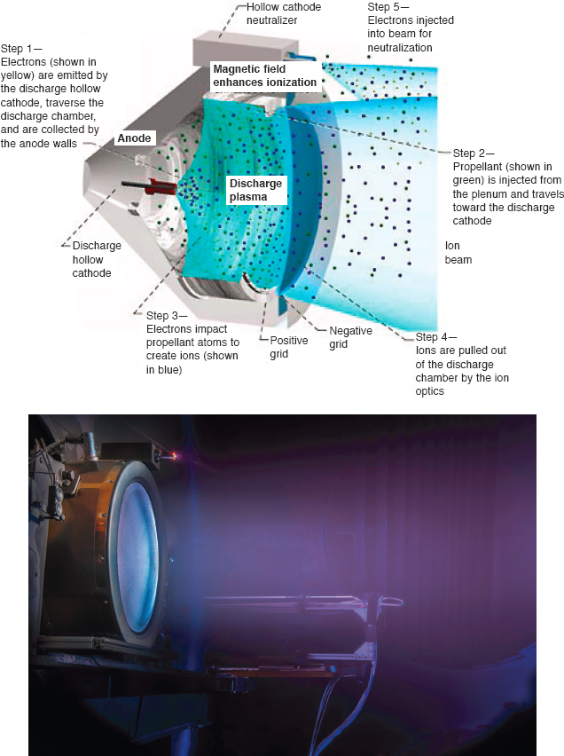
Ion thrusters use two or more parallel grids with a voltage applied to each to extract and accelerate ions created in a discharge chamber upstream of the grids (see Figure 3.3). Because ions are extracted and accelerated through the grids, a cathode neutralizer is needed to emit electrons to prevent a charge imbalance from forming. Charge separation in the grid assembly limits the maximum thrust density of ion thrusters, meaning that 100 kWe class ion thrusters are likely quite large. Ion thruster M&S is well developed, with good predictive performance and lifetime models that will support scaling to 100 kWe class thrusters. The primary area of uncertainty in ion thruster M&S is the impact of ground test facilities on long-duration thruster life tests.
With Hall thrusters (see Figure 3.4), propellant is injected through an annular channel and ionized by electrons trapped by an applied radial magnetic field. A voltage difference is applied between the anode, which usually serves as the propellant injector at the upstream end of the channel, and a downstream hollow cathode that supplies the electrons to the channel. The mixture of electrons and ions in the acceleration zone means that the thruster does not have the thrust density limitation associated with ion thrusters, although other lifetime considerations limit the achievable thrust densities. As with ion thrusters, M&S tools for Hall thrusters are well advanced and will support scaling to 100 kWe thrusters, although ground testing of high-power Hall thrusters has revealed that interactions among the test facility, the thruster, and its conducting plasma plume can impact the performance and lifetime
___________________
20 D. Hervol, L. Mason, A. Berchenough, and L. Pinero, “Experimental Investigations from the Operation of a 2 kW Brayton Power Conversion Unit and a Xenon Ion Thruster,” NASA TM—2004-212960, Paper presented at the Space Technology and Applications International Forum (STAIF 2004), Albuquerque, NM, 2004.
21 J.H. Gilland, M.R. Lapointe, S. Oleson, C. Mercer, E. Pencil, and L. Mason, “MW-Class Electric Propulsion System Designs for Mars Cargo Transport,” Proceedings of the AIAA SPACE 2011 Conference & Exposition, Long Beach, CA, 2011.

measurements in ways that are not fully understood as of this writing.22,23 This introduces uncertainty into current predictions of in-space performance and lifetime for high-power Hall thrusters.
Table 3.2 provides a list of representative state-of-the-art ion and Hall thrusters along with their operating and performance attributes. This table includes the following four flight systems:
- The Aerojet Rocketdyne XR-5 Hall thruster, which is currently in use on several DoD and commercial spacecraft and has been ground tested to more than 10,000 h.
- NASA’s Advanced Electric Propulsion System (AEPS) Hall thruster, which is undergoing flight development, has a projected lifetime of more than 20,000 h and is slated for NASA’s Lunar Gateway Power and Propulsion Module.
- NSTAR ion thruster, which flew on Deep Space 1 (1998) and DAWN (2007), was life tested to more than 30,000 h.
- NASA’s Evolutionary Xenon Thruster–Commercial (NEXT-C) thruster, which was ground tested for 50,000 h and is slated for the Double Asteroid Redirection Test mission (2021).
All flight thrusters also have flight PPU and PMS subsystems, although they are designed to interface with a solar photovoltaic power system, not a nuclear power source.
TABLE 3.2 Examples of State-of-the-Art Hall and Ion Electric Propulsion Thrusters and Power Processing Units (PPUs)
| Thruster | Thruster Type | Power (kWe) | Status | Propellant | Thruster | PPU α (kg/kWe) | References | ||
|---|---|---|---|---|---|---|---|---|---|
| Isp (s) | ƞ (%) | α (kg/kWe) | |||||||
| XR-5 | Hall | 4.5 | Flight Operations | Xenon | 2,020 | 56 | 2.7 | 2.8 | AIAA-2010-6698, AIAA-2005-3682 |
| AEPS | Hall | 12.5 | Flight Development | Xenon | 2,800 | 67 | 3.8 | 4.0 | AIAA 2020-3626, A-R Spec Sheet |
| NASA-457M | Hall | 50 | Laboratory (inactive) | Xenon | 2,740 | 62 | 2.0 | AIAA 2012–3940 | |
| XR-100 | Hall | 100 | Laboratory (active) | Xenon | 2,570 | 63 | 2.3 | IEPC-2017-228 | |
| NSTAR | Ion | 2.3 | Flight Operations | Xenon | 3,120 | 60 | 3.6 | 6.4 | https://www1.grc.nasa.gov/space/sep/gridded-ion-thrusters-next-c/ |
| NEXT-C | Ion | 6.9 | Flight Qualification Complete | Xenon | 4,155 | 70 | 2.0 | 5.1 | AIAA 2020-3604 |
| Herakles | Ion | 28.5 | Development (inactive) | Xenon | 7,000 | 70+ | 1.8 | 2.5 | AIAA 2005-3890, AIAA 2005-3891 |
NOTE: α, specific mass; ƞ, efficiency.
___________________
22 M.J. Sekerak, et al., “Mode Transitions in Magnetically Shielded Hall Effect Thrusters,” Proceedings of the 50th AIAA/ASME/SAE/ASEE Joint Propulsion Conference, Cleveland, OH, 2014, https://doi.org/10.2514/6.2014-3511.
23 E. Dale, B. Jorns, and A. Gallimore, “Future Directions for Electric Propulsion Research,” Aerospace 7(9):120, 2020, https://www.mdpi.com/2226-4310/7/9/120/htm.
Current flight EP thrusters have a maximum power of 6.9 kWe, which are not practical for a MWe-class NEP system, given the large number of thrusters that would be required. Several thrusters have undergone laboratory tests for tens of hours at 50 kWe and above, including two of the Hall thrusters listed in Table 3.2 and two less-developed concepts: the MPD and VASIMR® thrusters. The highest-power Hall thruster tested to date was the XR-100, which was operated as an integrated thruster-PPU-PMS system for several hours in an attempt to reach the goal of 100 h steady-state operation set by the NASA NextSTEP Advanced Propulsion Systems program.24
MPD thrusters (see Figure 3.5) use the Lorentz body force that is generated by the interaction of the electrical current driven through ionized propellant with the magnetic field generated by this current. The applied magnetic field from an electromagnet may be used to enhance the acceleration process. MPD thrusters have among the highest thrust and power densities of any EP thruster. While they can operate on a number of propellants, lithium appears to be most promising for NEP applications.
The VASIMR thruster (see Figure 3.6) uses radio waves in a two-stage process to create and heat plasma that is then expanded through a magnetic nozzle for thrust production. The status of these more immature but higher power concepts is given in Table 3.3. Neither thruster has undergone significant life testing in recent years. A Soviet-era 500 kWe lithium MPD thruster reportedly underwent a 500-h life test with promising yet uncertain results, and the Ad Astra Rocket Company is working toward the goal of a 100-h test of a 100 kWe VASIMR thruster.25 While limited M&S tools exist for both MPD and VASIMR, overall, they are more rudimentary and have not been well-validated compared to those for Hall and ion thrusters.
Power Processing Unit and Propellant Management System
The state-of-the-art PPU for Hall thrusters is arguably the one associated with the 4.5-kW XR-5 flight unit. This PPU has an input power conversion efficiency of at least 92 percent with an input voltage of 70 V DC, and it has a mass of 12.5 kg for a PPU specific mass of 2.8 kg/kWe. The XR-5 also includes a state-of-the-art PMS. The 12.5-kWe AEPS Hall thruster (along with its associated PPU and PMS), under development by Aerojet Rocketdyne for NASA’s Project Artemis (launch planned in 2024), is the next evolution of Hall thruster, PPU, and PMS. A laboratory PPU for the X3 Hall thruster was developed and tested during NASA’s NextSTEP program and ran for tens of hours. As noted above, all of these PPUs are designed for use with photovoltaic arrays, not nuclear power sources. As with PMAD, the M&S tools for PPUs and PMS are well established, but the specific component, circuit, and fluid models appropriate for MWe-class systems have not been developed. PPU M&S development and validation will likely prove challenging due to the high power and high radiation environments for the electrical components.
TECHNOLOGY REQUIREMENTS, RISKS, AND OPTIONS
The baseline mission requires an NEP system whose performance far exceeds that of existing flight systems in terms of power, specific mass, and reliability, though limited subscale demonstrations of several relevant technologies have been completed. In addition, radiation-hardened power electronic systems for PMAD or PPUs at megawatt electric power levels have never been developed. Existing thruster concepts such as Hall thrusters and ion thrusters can meet Isp and efficiency requirements, but thruster power levels must increase by an order of magnitude compared to current and near-term solar electric propulsion (SEP) flight systems. Higher power MPD or VASIMR thrusters are less mature. System lifetimes and reliability are poorly understood at megawatt electric power levels.
EP propellant management will essentially be a relatively straightforward scaling of current flight practice and design for systems that use propellants stored as a gas or liquid. (A feed system for MPD thrusters that use
___________________
24 NASA, “Advanced Electric Propulsion NextSTEP BAA Activity–Completed Technology Project (2015-2018),” https://techport.nasa.gov/view/33078, accessed May 22, 2021.
25 V.P. Ageyev, V.P. Ostrovsky, and V.A. Petrosov, “High-current Stationary Plasma Accelerator of High Power,” Proceedings of the 23rd International Electric Propulsion Conference, 1993, http://electricrocket.org/IEPC/IEPC1993-117.pdf.
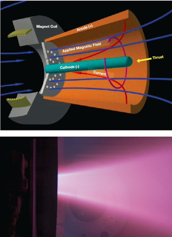
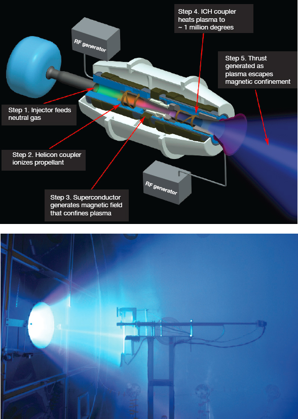
TABLE 3.3 High-Power Research Thruster and Power Processing Unit (PPU) Concepts
| Thruster | Thruster Type | Power (kW) | Status | Propellant | Thruster | PPU α (kg/kWe) | References | ||
|---|---|---|---|---|---|---|---|---|---|
| Isp (s) | ƞ (%) | α (kg/kWe) | |||||||
| SX3 | MPD | 66 | Laboratory | Argon | 3670 | ~ 50 | IEPC 2017-339 | ||
| ALPHA2 | MPD | 245 | Designed | Lithium | 6200 | ~ 60 | 0.5 | 1.5 | AIAA 2005-3894 |
| VASIMR | Radiowave-driven magnetized plasma electrothermal | 200 | Laboratory | Argon | 5000 | ~ 60 | 2.8 | 2.85 | AIAA 2019-3810, AIAA 2018-4417, AIAA 2017-4630,IEPC-2013-149 |
NOTE: α, specific mass; ƞ, efficiency.
lithium propellant stored as a solid would require further development.) In either case, as discussed in Chapter 1, a 1 MWe-class NEP system capable of executing the baseline mission also requires augmentation by a chemical propulsion system using cryogenic propellants and assumes minimal boiloff using cryocooler technology. This technology will have to be matured in parallel with NEP development.
Integrated System
The NEP system is a complex system, with performance requirements for power level, specific mass, Isp, efficiency, lifetime, and reliability propagating throughout the subsystems in terms of temperature and power density requirements. Achieving a specific mass of 20 kg/kWe for the entire NEP system scaled for the baseline mission is a significant challenge that drives the reactor, power conversion, and heat rejection subsystems to higher operating temperatures, and drives EP subsystems to efficient power distribution, processing, and thrust production. The multiple subsystems of an NEP system must demonstrate adequate performance and reliable operation of interconnected subsystems across all phases of mission operations as well as unexpected transients during abnormal operating conditions. The NEP system relies on a wide spectrum of physics and engineering: neutronics, thermal hydraulics, high-temperature materials, fluid mechanics, turbomachinery, power electronics, electromagnetism, and plasma physics. Detailed subsystem and system M&S tools will need to be developed to account for subsystem interactions. While this will require definitions of interfaces throughout the development of the subsystems, such a process has been successfully demonstrated for the significantly lower power levels associated with SEP robotic missions in Earth orbit and interplanetary space. NASA’s most recent credible analysis of an integrated NEP system was conducted as part of Project Prometheus (2003 to 2005) at an order of magnitude lower power level. Demonstrating Prometheus-level technology at the power level and scale required for the baseline mission while meeting goals for specific mass is a considerable challenge.
FINDING. NEP Power Scaling. Developing a MWe-class NEP system for the baseline mission would require increasing power by orders of magnitude relative to NEP system flight- or ground-based technology demonstrations completed to date.
Reactor Subsystem
Chapter 1 specifies that the NEP system of interest would operate at 1 to 2 MWe, have a specific mass of no more than 5 kg/kWe for the EP system, a specific mass of no more than 15 kg/kWe for the other five subsystems combined, and a maximum fuel temperature high enough to heat reactor coolant to a temperature of approximately
1200 K at the reactor outlet. For the baseline mission, such a system would experience reactor fuel burnup of about 4 percent over a period of about 4 years. These parameters are within the envelope of irradiation tests performed on fuel systems in prior space reactor programs. Key reactor concept decisions to be finalized include fuel enrichment (HEU versus HALEU)26 and neutron spectrum (fast versus moderated), which in turn will drive the selection of specific fuel, cladding, and structural materials for the reactor. The reference fuel system for a fast-spectrum reactor of Nb-1%Zr clad UN fuel is backed up by extensive irradiation testing, although all of these tests were performed more than 25 years ago. Available reactivity control materials are sufficient to produce a highly reliable reactor system. Technology recapture activities will be needed for the manufacturing of legacy materials and reactor components.
Shield Subsystem
A variety of feasible radiation shield options are available that would enable suitable shielding for the crew and sensitive electronic components at distances of about 50 to 100 m from the reactor over a 4-year life. As noted previously, shielding consists of layers of low atomic number materials (e.g., Be, LiH, and B4C) to attenuate neutrons, and high atomic number materials (e.g., W) to attenuate gamma rays. Most of these shields work best at temperatures between about 300 and 900 K, so cooling below the reactor operating temperature is desirable; most hydride shield materials rapidly lose hydrogen at higher temperatures.
Power Conversion Subsystem
Power conversion subsystems couple with the reactor at maximum temperatures comparable to the reactor coolant outlet temperature. For dynamic power conversion, this requires turbine material temperatures of 1100 to 1200 K, requiring at least superalloy materials or refractory metals if temperatures higher than 1150 K are necessary. For the targeted power level of 1 to 2 MWe, individual converter output power levels of 200-800 kWe would be needed, with the specific selection depending on component and system level performance, lifetime, and reliability trade studies. Power conversion subsystem lifetimes less than that required for the entire mission (2 to 4 years depending on mission assembly and operation requirements) would require duplicate components or subsystems to ensure mission success. A direct-drive approach for powering thrusters from an AC conversion system would require AC output at 400 to 650 V for Hall thrusters or ~3000 V for ion thrusters, to be rectified for thruster beam power.
Operating temperatures for the power conversion subsystems tested to date are at the minimum acceptable level to meet NEP needs. Brayton energy conversion technologies are more advanced than other types, but they introduce new types of risks, and demonstrated power levels for space-qualified systems are orders of magnitude below that required for a 1 to 2 MWe system. A Rankine power conversion system, although used extensively in terrestrial systems, would pose additional risks associated with handling a two-phase flow in zero gravity. Liquid metal working fluids adopted for some power conversion options would also likely introduce the need for refractory metals in the power conversion sections. Advanced NEP systems will likely be able to convert perhaps 20 to 35 percent of the thermal energy from the reactor coolant into electrical power.27
Heat Rejection Subsystem
Temperatures of at least 500 K are necessary for radiators to reject heat in a mass efficient manner. At these temperatures, a total radiating area on the order of 1500 m2 to 3000 m2 (single sided) would be required for a 1 to 2 MWe NEP system. These radiators must also provide high thermal conductivity and operate reliably for the entire reactor and power system operating time (2 to 4 years depending on mission design). Initial studies for the NEP module used carbon composite structure and water-filled heat pipes in conjunction with a pumped
___________________
26 See Chapter 5 for a discussion of HEU versus HALEU fuels.
27 G.R. Longhurst, E.A. Harvego, B.G. Schnitzler, G.D. Seifert, J.P. Sharpe, D.A. Verrill, K.D. Watts, and B.T. Parks, Multi-Megawatt Power System Analysis Report, INEEL/EXT-01-00938 Rev. 01, 2001, https://inldigitallibrary.inl.gov/sites/sti/sti/2688772.pdf.
sodium-potassium alloy liquid metal loop to reach an area specific mass of about 7.7 kg/m2, including all supporting pumps; this is similar to the approach on the Prometheus system design. A reduction in specific mass for this subsystem is possible by using higher temperature panels, but that would propagate back throughout the NEP system to higher reactor and power conversion temperatures. Another way to reduce the mass of this system is to use a constant-rejection temperature cycle such as the Rankine cycle in which the working fluid undergoes a phase change, instead of the Brayton cycle in which the working fluid decreases in temperature throughout the heat rejection portion of the cycle. This change would require additional development of the power conversion subsystem to address two-phase flow in zero gravity. A third option for reducing the mass of the heat rejection subsystem is to develop lower-mass high-temperature materials.
With such a large area, stowing, deploying, and on-orbit assembly of the heat rejection system will be significant challenges. To fit in the shroud of likely launch vehicles, the radiator panels and fluid transport systems for distributing heat to the heat pipes would need to be folded without breaching the seals for the coolant piping, and this complex assembly would need to survive launch environments. There is limited flight heritage in this area.
Power Management and Distribution (PMAD) Subsystem
Developing a PMAD subsystem for a MWe-class NEP system with a low specific mass will require either efficient, high voltage AC power transmission to a thruster PPU (see below), or direct-drive DC transmission at 400 to 800 V (assuming use of Hall thrusters) for rectification. Higher voltage transmission could result in lower mass power distribution due to the reduced current requirements. For state-of-the-art silicon components, the low (350 K) operating temperature for these electronics implies large area requirements for heat rejection. In order to meet the specific mass requirements for the baseline mission (including heat rejection), PMAD efficiencies of at least 90 to 95 percent will be needed to reduce waste heat. Additionally, as was observed in the JIMO program, radiation hardening to protect electronics against radiation damage from both the NEP system and from the space environment will be required. PMAD designs will need to address reliability in terms of switching and power regulation for the 2- to 4-year life of the baseline mission. The limited availability of highly reliable, radiation-hardened electronic components may limit the voltage and current options for the PMAD system.
Further improvement in performance might be realized with higher temperature semiconductor materials, such as SiC or GaN. These have been considered in past MWe NEP studies, but performance and life demonstration are required to determine their actual efficacy for the baseline mission. SiC can withstand higher operating temperatures of the power electronics (for the PMAD subsystem and the PPU in the EP subsystem), thereby reducing the radiator area and mass, but performance and operational life at megawatt electric power levels would have to be demonstrated for a space relevant environment.
Electric Propulsion Subsystem
Thruster performance requirements are to some extent dependent on power system specific mass and power levels. As specified in Chapter 1, the Isp goal is 2,000 s or more, with thruster efficiencies greater than 50 percent in order to provide enough acceleration for the power levels, payloads, and trip times. Thruster power levels of 100 kWe or more allow for a reduction in system complexity in terms of the numbers of thrusters, PPUs, and PMSs that must be integrated. Similarly, the baseline mission imposes a total system operating time of at least 2 years, which is approximately 20,000 h. Lifetime must therefore be a minimum of 2 years, or, with the typical 50 percent margin required for space systems, 3 years or 30,000 h, or spare units will have to be included, with a commensurate mass penalty. In addition, the system must be available for the full mission life of about 4 years, which includes time for launch, in-space assembly, and the round trip to Mars.
Thrusters
Existing thrusters cannot meet all mission requirements. Flight qualified or demonstrated thrusters such as Hall and ion thrusters have operated at 4.5 and 7 kWe, respectively, with the next anticipated qualified thruster to be the
AEPS Hall thruster at 12.5 kWe. All of these thrusters, however, are expected to meet the lifetime requirement of at least 20,000 h: the 4.5 kWe Hall thrusters were tested for more than 10,000 h with no life limitations identified, the 7 kW ion thruster was tested to 50,000 h, and the AEPS thruster has a design life (as yet unverified) of more than 23,000 h. Testing plasma thrusters for extended periods at power levels greater than approximately 20 kWe poses facility challenges that have limited development at these power levels (see below).
Scaling thrusters to higher power levels at the required Isp represents a risk in terms of the increased power density or thruster size. In the case of ion thrusters, this represents an increase in grid area of an order of magnitude, while maintaining inter grid spacings within less than 1 mm. In the case of Hall thrusters, either channel power density must be increased, which introduces heating and lifetime issues, or channel and thruster diameter must increase for the same reason as the ion thruster. Laboratory models have been tested to address this scaling, including the use of multiple concentric channels.28 For the ion thruster, the annular ion thruster mitigates grid spacing issues by providing a central support to the grids.29 For the Hall thruster, multiple, nested channels have been tested to 100 kW power levels.30 Both concepts have been tested only for short periods of time and further testing is needed.
MPD and VASIMR® thrusters, while considered to be better able to process high power, also require higher powers to operate efficiently. As a consequence, demonstrated performance and life testing are lacking. High-power thruster testing, in general, has not been prioritized because traditional spacecraft cannot provide the power levels necessary to operate them in space. Lithium MPD thruster research to date has demonstrated promising results; there are few data on performance, electrode lifetime, and thermal response at power levels above 250 kWe.31,32 MPD thrusters are high-current, low-voltage devices, which impose heating and switching issues for the PPU and PMAD. VASIMR is at a lower stage of development in terms of both the thruster performance and engineering. Work to date has not demonstrated the physics of the magnetic nozzle used to accelerate the plasma, the life of the device, and the implementation of superconducting magnet coils, all of which are required to meet efficiency requirements.33
Power Processing Unit
The PPU will be quite different depending whether a direct-drive or standard PPU approach is ultimately selected. If a standard PPU approach is needed, then the PPU architecture, requirements, and risks will be similar for those of other EP systems, albeit at a much higher power level. This effort would build on the recent PPU development for NASA’s NextSTEP program, which demonstrated short-term operation at 100 kWe for a single thruster. For a direct-drive approach, the PPU is greatly simplified, but it still must provide power and control for cathode operation, magnet coils, thruster current control feedback to the PMS, thruster ignition and shutdown transients, thruster throttling (if required), and any thruster-to-thruster interactions that might occur in a multi-thruster system where the plasma plumes interact. Additionally, PPUs may be required to manage power during fast transients that occur normally during thruster operation and during component failures, which can induce large power transients in an integrated system and may be exacerbated for multi-thruster systems. For any PPU
___________________
28 S.J. Hall, B.A. Jorns, A.D. Gallimore, H. Kamhawi, T.W. Haag, J.A. Mackey, J.H. Gilland, P.Y. Peterson, and M.J. Baird, “High-Power Performance of a 100-kW Class Nested Hall Thruster,” IEPC-2017-228, presented at the 35th International Electric Propulsion Conference Georgia Institute of Technology, October 8–12, 2017.
29 M.J. Patterson, R. Thomas, W. Crofton, J. Young, and J.E. Foster, “High Thrust-to-Power Annular Engine Technology,” 51st AIAA/SAE/ASEE Joint Propulsion Conference, FL, July 27-29, 2015, https://doi.org/10.2514/6.2015-3719AIAA-2015-3719.
30 S.W.H. Shark, S.J. Hall, B.A. Jorns, R.R. Hofer, and D.M. Goebel, “High Power Demonstration of a 100 kW Nested Hall Thruster System,” Proceedings of the AIAA Propulsion and Energy Forum, Indianapolis, IN, 2019.
31 V.P. Ageyev, V.P. Ostrovsky, and V.A. Petrosov, “High-Current Stationary Plasma Accelerator of High Power,” 23rd International Electric Propulsion Conference, IEPC-93-117, July 1993.
32 E.Y. Choueiri, Advanced Lithium-Fed Lorentz Force Applied Field Accelerator, Final Technical Progress Report, Princeton University, December 2007.
33 J.P. Squire, M. Carter, F.R. Chang Diaz, A. Corrigan, L. Dean, J. Farrias, M. Giambusso, G. McCaskill, and T. Yao, “Steady-State Testing at 100 kW in the VASIMR®VX-200SS Project,” AIAA 2019-3810, AIAA Propulsion and Energy 2019 Forum, 2019, https://doi.org/10.2514/6.2019-3810.
architecture, PPU components must operate at efficiencies over 90 percent and/or at temperatures warmer than is possible with state-of-the-art silicon components, to reduce thermal management mass in the EP subsystem.
Based on mission studies to date, overall EP subsystem specific mass will need to be less than ~4.5 kg/kWe to keep overall NEP system specific mass below 20 kg/kWe. The NextSTEP program goal for 100 kWe class EP subsystems, including the thruster, PPU, and PMS, was a specific mass less than 5 kg/kWe. While a significant challenge, a potential advantageous factor may be the use of direct-drive PMAD, in which the power from the power conversion subsystem is already configured to match thruster beam requirements. This approach could substantially reduce PPU specific mass; however, only laboratory simulations of direct drive have been performed, with laboratory power supplies supplying the other low voltage and power components needed by a thruster, and without a full assessment of control during transients. For instance, the simulated direct drive of an ion thruster by a Brayton conversion device was only for the 1100 V thruster beam power; other thruster components such as cathodes were operated using laboratory power supplies.34 Additionally, system reliability and fault protection requirements for flight systems will increase the PPU mass.
Propellant Management System
The two most mature thruster concepts, ion and Hall thrusters, both use xenon propellant. There is extensive flight experience with the storage and distribution of xenon for orbital and interplanetary missions. Xenon is stored at high pressure as a supercritical gas, with pressure and flow regulation to the thrusters. Scaling to higher power will introduce the need for larger tanks; some of this is being addressed incrementally in the design of NASA’s Power and Propulsion Element, which will incorporate a 50 kWe SEP system and carry 2,500 kg of xenon propellant.35,36 Of course, this is still orders of magnitude below the amount of propellant (which may be around 100,000 kg) that will be required for the baseline mission, and it is not clear how the propellant tank mass will scale for these very large propellant loads.
TESTING, MODELING, AND SIMULATION
An NEP system has multiple subsystems performing separate but necessary functions to convert thermal energy from the reactor to thrust. This introduces both challenges and opportunities to demonstrating the ability of the whole system to perform the desired mission. The challenge lies in the integration of the system and the demands of ground testing nuclear and nonnuclear subsystems; the opportunities lie in the fact that the system can be disaggregated into subsystems which can be demonstrated separately up to the point of integration. This is an approach that has been used successfully and repeatedly in SEP missions. Similarly, the planned use of EP on earlier Artemis missions offers some opportunities to advance integration and M&S capabilities for NEP.
The testing approach for NEP reflects both its level of immaturity and its separability into subsystems for some aspects of its development. Testing will be necessary at two levels. Initial testing will validate reactor fuels, materials, and selected components from each subsystem. Subsequent testing will validate subsystem-level performance and lifetime. This second phase will also establish subsystem interface requirements for the overall system. The dramatic increase in power level from today’s kilowatt-electric systems to megawatt electric levels will require an assessment of test facilities for each subsystem to determine facility constraints and availability, as well as to identify any necessary modifications or construction to support the testing requirements. As discussed further below, it is essential that M&S tool development and validation proceed in parallel with testing.
The overall NEP system testing and qualification will involve multiple subassemblies, components, and subsystems developed and tested separately, with integration demonstrated after subsystem maturation.
___________________
34 D. Hervol, L. Mason, A. Berchenough, and L. Pinero, “Experimental Investigations From the Operation of a 2 kW Brayton Power Conversion Unit and a Xenon Ion Thruster,” NASA TM—2004-212960, Paper presented at the Space Technology and Applications International Forum (STAIF 2004), Albuquerque, NM, 2004.
35 The Power and Propulsion Element is a spacecraft that is being developed as part of NASA’s Project Artemis to return astronauts to the Moon.
36 D.A. Herman, T. Gray, I. Johnson, T. Kerl, T. Lee, and T. Silva, “The Application of Advanced Electric Propulsion on the NASA Power and Propulsion Element (PPE),” IEPC–2019–651, Paper presented at the 36th International Electric Propulsion Conference, Vienna, Austria, 2019.
NEP system designs allow much of the integrated system performance to be accomplished in a nonnuclear, electrically heated environment assuming that the neutronic feedback components associated with the reactor subsystem behavior are properly represented computationally and the test article is adequately instrumented to measure physical conditions that would impact core reactivity (e.g., measurement of thermal expansion with increasing temperature). Thus, an integrated ground test could involve all but the reactor subsystem, which could be emulated via simulation and electrical heating, and would not require nuclear heating or full radiator deployment. This can save both time (i.e., reduce schedule) and program cost. However, full retirement of risk for the reactor subsystem and its components would require ground testing in a representative nuclear environment.
With sufficiently rigorous M&S and ground testing, it may be feasible to conduct the first test of a fully integrated, full-scale NEP system during the first cargo mission. This would require the NEP system for that mission to include all of the instruments necessary to fully characterize system performance and to enable projecting how the system would perform during a two-way mission, as will be case during crewed missions.
Separate effects testing for materials development and characterization and subsystem performance tests would likely include the following:
- Reactor. Required tests range from fuel, fuel element, and core materials tests to integrated reactor tests. Development of the reactor subsystem would be conducted in concert with the modeling of neutronics and thermal hydraulics, informed by results from fundamental fuels and materials testing. This would begin as materials and fuel element testing in a test reactor facility to characterize material properties under representative temperature and irradiation conditions, assuming that data are not already available for the selected materials, followed by fuel element subassembly testing, also within a test reactor. This would be followed by testing of the full reactor subsystem under a suitable pressure and thermal environment to demonstrate power and neutronic performance, controllability, reliability, and life under both nominal and off-nominal conditions. Tests of the reactor subsystem would include ZPC, low power, and full power testing. Testing at full power will require transferring heat to the environment via use of an integrated heat exchanger or integration with the power conversion subsystem. Existing reactor facilities can likely support separate effects and materials testing. ZPC testing of a MWe-class NEP system can also likely be supported via existing facilities, with modification and investment, or in facilities currently being planned for development of terrestrial reactor technologies. The adequacy of facilities for full power testing of a MWe-class NEP system is less certain. As discussed in Chapter 5, facilities are currently under development for MWe-class power reactors that may be capable of supporting reactor subsystem tests for NEP if they are available for use within the timeframe required.
- Shield. Shield design and materials testing for a 1 to 2 MWe reactor (4 to 8 MWt) at temperatures suitable for NEP are relatively mature. Relevant test and modeling data from many prior space nuclear programs are available, which would allow a shield to be readily designed and tested. Component testing for shielding system designs could be supported using accelerator-driven irradiation sources that produce the necessary neutron and gamma environment to emulate the source from the reactor subsystem. In this manner, shielding performance could be validated with regard to radiation attenuation as well as demonstrating thermal management systems. However, these facilities may be limited in their ability to represent external, space-radiation sources that may also impact the thermal management in the shielding structure. Shield testing could also be conducted in concert with reactor testing.
- Power conversion. Power conversion subsystem tests will also range from fundamental materials tests for heat exchangers, turbines, bearings, etc., to integrated, electrically heated power conversion subsystem tests. A similar approach has been used for lower power Brayton and Stirling systems in the past. Vacuum or low-pressure operation with a thermally relevant background environment will be required. The subsystem tests would include a simulated PMAD and thruster load and would evaluate system response to all anticipated power system transients. The specific interfaces for this test will depend on whether or not a direct-drive approach is selected. Power conversion subsystems could be tested using electrical heat sources at facilities at NASA Glenn Research Center and Plum Brook Station.
- Heat rejection. Tests will range from heat pipe materials to multiple integrated panel tests in a suitable thermal environment. Heat rejection panels would be tested using heat supplied to the panel loop at an equivalent temperature and heat exchanger performance as designed for the NEP system, with heat rejection to a relevant sink temperature for the NEP mission. Subsystem response to planned or unplanned power system transients (e.g., power adjustments during startup, operation, or shutdown) would be assessed. Testing would include sufficient panels to fully evaluate any articulation or joints required by the need for on-orbit deployment. It is not clear whether sufficiently large facilities exist today for testing of the full heat rejection subsystem, although several facilities exist at NASA and DOE for testing multiple panels and confirming deployment mechanisms.
- PMAD. The high power involved in the NEP will likely require extensive electrical component testing to validate component performance and lifetime in relevant environments, as well as subsystem testing with simulated power conversion subsystem and EP subsystem loads. Because this system is an electric-to-electric interface, much of this testing can be accomplished with simulated input power and loads, and facilities exist for full-scale hardware testing of this type. For a direct-drive approach, the coupling of the power conversion to the EP subsystem would be demonstrated, similar to the low-power test completed using Prometheus components, but designed for the selected EP system. This test series would include an evaluation of all transients during the startup, shutdown, normal operational phases, and failure scenarios to demonstrate the robustness of the entire subsystem. It will also require validation of the PMAD in a representative nuclear environment.
- EP. Testing involves thruster performance over the intended EP lifetime, as well as string integration tests that demonstrate the PPU, PMS, and thruster interfaces during all phases of operation. Testing would be conducted such that it validates the subsystem lifetime with the expected electrical and thermal interfaces in the correct radiation environment. For a direct-drive system, the PPU will be simplified, but it will still be required as previously described. Testing would be informed by experience gained from NASA’s AEPS development program and the flight operation of NASA’s Power and Propulsion Element, both in terms of facility effects and thruster behavior in space. Electrical input from the PMAD (direct drive, if chosen in the design) would be simulated as input to the thrusters during the ground test to demonstrate feasibility. While many laboratory tests of 100 kWe class EP thrusters have been conducted, high-fidelity EP thruster test facilities are limited today to less than 50 kWe, and there is significant uncertainty as to the test facility requirements necessary to properly simulate the space environment. A significant effort will be required to establish EP thruster test facilities for 100 kWe thrusters capable of supporting high-fidelity long-duration life tests, and even more so to support multi-thruster tests to evaluate thruster interactions in a multi-thruster array.
As the subsystem elements mature, integrated system ground testing would occur at laboratory, engineering, and flight model stages of the development program. Potential tests could include, for example, a single electrically heated power conversion unit and heat rejection panel in a vacuum facility with relevant sink temperature, connected by a PMAD system to a thruster operating in another vacuum chamber. This would likely require several large vacuum chambers, as the heat and plasma loads of 50 to 100 kWe power conversion and thruster units would likely overload a single existing facility. Testing would include all phases of operation and potential failure mechanisms to ensure a full understanding of the NEP system dynamic response. It will also be necessary to evaluate multi-thruster interactions to ensure that no unexpected behaviors occur due to the presence of multiple plasma plumes during ignition, operation, and shutdown.
NEP testing will require extensive M&S, both to design the subsystems and to define the interfaces between subsystems to simulate flight conditions. Testing will provide the necessary data to validate the physics models embedded within the broader system and subsystem M&S software. Modeling of the steady-state and dynamic operation of terrestrial nuclear systems is relatively mature, but for materials and designs of interest to NEP, the coupled neutronics and thermal hydraulics models must be informed by initial fuel and material testing. While some materials under consideration for the reactor subsystem have an established database characterizing their fundamental properties (pre- and post-irradiation), it is likely that the database even for “known” materials does
not encompass the full range of operating conditions anticipated in an NEP system. EP operation on the ground relative to that observed in space is still being used to assess and update models, both in terms of performance and thruster life. EP models for performance and lifetime will be augmented using flight data from future missions. Additional instrumentation of NASA’s Power and Propulsion Element flight system to evaluate thruster plumes, as well as results from ongoing and planned life tests of the AEPS thrusters, will provide data to further improve and validate current models for use in scaling thrusters to higher powers.
System-level modeling that dynamically couples the performance and transients across all subsystems will also be vital to the feasibility of NEP development. While this is something that is done routinely for terrestrial power systems up to the load, an NEP system will introduce additional challenges. At each interface, thermal, flow, electrical, and neutronic inputs (and outputs) will be required, and an overall system model, benchmarked and validated by system and subsystem tests, will be required.
Subscale in-space testing will not be sufficient to eliminate the need for full-scale ground testing. Extrapolating high power density nuclear power systems over one or two orders of magnitude from early, lower power feasibility flights introduces uncertainty of controllability, thermal hydraulic and electrical interactions, and the potential for schedule slippage. The long-life demonstration requirement (2 to 4 years) for all subsystems precludes repeated life testing either on the ground or in space in order to meet the required flight schedule.
FINDING. NEP Modeling and Simulation, Ground Testing, and Flight Testing. Subscale in-space flight testing of NEP systems cannot address many of the risks and potential failure modes associated with the baseline mission NEP system. With sufficient M&S and ground testing, including modular subsystem tests at full scale and power, flight qualification requirements can be met by the cargo missions that will precede the first crewed mission to Mars. Fully integrated ground testing may not be required.
RECOMMENDATION. NEP Modeling and Simulation, Ground Testing, and Flight Testing. To develop a nuclear electric propulsion (NEP) system capable of executing the baseline mission, NASA should rely on (1) extensive investments in modeling and simulation, (2) ground testing (including modular subsystem tests at full scale and power), and (3) the use of cargo missions as a means of flight qualification of the NEP system that will be incorporated into the first crewed mission.
DEVELOPMENT AND DEMONSTRATION ROADMAP
The roadmap in Figure 3.7 shows key milestones and when they would need to be achieved to execute the baseline mission: launching a crewed mission to Mars in 2039 preceded by an initial cargo mission in 2033.
Executing the baseline mission to deliver humans to Mars in 2039, as well the precursor cargo missions, requires some very near-term design and a dedicated development, testing, and demonstration program. The lack of support for NEP technology development over the past decade has resulted in large uncertainty surrounding the appropriate design choices and development plan. The first design selection is the determination of the preferred level of fuel enrichment (HEU or HALEU) and neutron spectrum (fast or moderated). All past technology and system studies of NEP have assumed HEU fuels; the selection of HALEU would introduce additional uncertainties that will have to be addressed. Second, a limited set of integrated mission, system, and vehicle architectures must be defined to allow selection of a small number of NEP system requirements upon which to base development and testing. It is essential that this development effort focus on the key design selections required to define the final NEP flight system. NASA mission studies to date have indicated that an NEP system specific mass of 20 kg/kWe, achievable with a 1200 K reactor, 1150 K power conversion temperatures, and reactor fuel burnup of 4 percent over 4 years, and Hall effect thrusters using direct-drive PMAD, are sufficient; but requirements and capabilities, as well as their sensitivity to potential component and subsystem development outcomes, have yet to be confirmed.
As of the end of 2020, there were no NEP component, subsystem, or system development efforts under way. Developing and producing crew-ready flight NEP systems by 2039 would therefore require a significant and rapid ramp-up of component level development and testing, as shown in Figure 3.7. The program structure combines initial technology development of reactor fuels, materials, and designs for each of the subsystems discussed
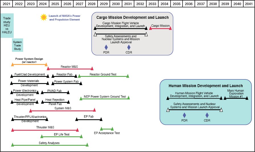
previously and assumes concurrent M&S, ranging from the physics to system levels, to address the system complexity. The roadmap also includes time for lifetime demonstration and validation testing for all NEP subsystems. Additionally, the proposed roadmap uses an early Mars cargo mission, to be launched in 2033, as the first flight of the NEP system, rather than conducting a subscale flight test.
An NEP ground testing program requires the adaptation or development of test facilities to adequately develop and qualify the full range of NEP subsystem and integration tests. This will require a full survey and assessment of relevant facility capabilities. Testing will be supported by the development and validation of M&S tools.37 M&S capabilities for current and planned efforts in terrestrial power may be useful. Thruster life and relationships between ground test data and in-space operation may be augmented by experience with SEP systems. However, due to the orders of magnitude difference in power levels between current systems and a MWe-class NEP system, some ground testing challenges will remain.
Operation of steady-state Hall thrusters for thousands of hours at 12.5 kWe has been demonstrated and is ongoing.38 This level of testing is in support of the planned flight of the NASA Power and Propulsion Element in 2024, which will provide extensive data on the correlation of ground testing to space operation of Hall thrusters. Additionally, 100 kWe Hall thrusters have been tested for dozens of hours; but they have not been flight qualified, and there is significant uncertainty as to how these test results would translate to in-space operation in terms of performance and lifetime. Testing at these levels has predominantly been performed at NASA Glenn Research Center.39 Therefore, a parallel effort to upgrade facilities enabling EP thruster testing to 100 kWe in an adequate environment, as well as the development of improved M&S tools and advanced diagnostics would be needed to support development of Hall thrusters for a MWe-class NEP system.
A chemical stage fueled by liquid oxygen (LOX) and liquid methane would be developed concurrently with the development of the NEP system. This stage would be developed in concert with the currently planned Artemis Mars Ascent engine, which is also expected to use a LOX/liquid methane propulsion system.
FINDING. NEP Prospects for Program Success. As a result of low and intermittent investment over the past several decades, it is unclear if even an aggressive program would be able to develop an NEP system capable of executing the baseline mission in 2039.
RECOMMENDATION. NEP Major Challenges. NASA should invigorate technology development associated with the fundamental nuclear electric propulsion (NEP) challenge, which is to scale up the operating power of each NEP subsystem and to develop an integrated NEP system suitable for the baseline mission. In addition, NASA should put in place plans for (1) demonstrating the operational reliability of an integrated NEP system over its multiyear lifetime and (2) developing a large-scale chemical propulsion system that is compatible with NEP.
SUMMARY
At a concept modeling and analysis level, NEP shows promise for the baseline mission. However, intermittent funding has resulted in very limited, if any, advance in its technology readiness since 2005, and that work focused on 200 kWe NEP systems, not the MWe-class system required for this application. The need to extrapolate from those results to a 1 to 2 MWe system required for the baseline mission without increasing specific mass results in considerable uncertainty in feasibility of this path on a timeline consistent with the baseline mission. In particular, uncertainty in fuel system architecture and the significant scaling of thruster requirements and thermal and power
___________________
37 J.E. Polk and J.R. Brophy, “Life Qualification of Hall Thrusters by Analysis and Test,” Paper 00547, Paper presented at the Space Propulsion 2018 Conference, Seville, Spain, 2018.
38 J. Frieman, H. Kamhawi, P. Peterson, D. Herman, J. Gilland, and R. Hofer, Completion of the Long Duration Wear Test of the NASA HERMeS Hall Thruster, 2019, doi:10.2514/6.2019-3895.
39 J. Dankanich, M. Walker, M. Swiatek, and J. Yim, “Recommended Practice for Pressure Measurement and Calculation of Effective Pumping Speed in Electric Propulsion Testing,” Journal of Propulsion and Power 33(3): 668-680, 2016, doi:10.2514/1.B35478.
management are considerable challenges. The reliability and lifetime requirements of such a system merit careful attention and the lack of any substantive integrated system test remains a challenge.
The present state of NEP technology and limited subsystem ground test facilities for reactors and high-power EP thrusters require near-term assessment. Advanced reactor test facilities are currently under development for terrestrial programs, but the extent to which those facilities would be able to contribute to the development of MWe-class NEP systems remains to be determined.
EP has benefited from gradual increases in power level for solar powered spacecraft. There are currently hundreds of kilowatt-electric-class spacecraft flying operationally, and a 40 kWe SEP system, using multiple 13 kWe thrusters, is projected to launch in 2024. However, testing thrusters at power levels above 50 kWe, particularly for in-space performance and lifetime, will challenge existing vacuum facility capabilities.
RECOMMENDATION. NEP Pace of Technology Development. If NASA plans to apply nuclear electric propulsion (NEP) technology to a 2039 launch of the baseline mission, NASA should immediately accelerate NEP technology development.


