
2
Impacts of Wind Turbine Generators on Marine Vessel Radar
NAVIGATION AND SAFETY USING MARINE VESSEL RADAR
The Marine Transportation System (MTS; the waterways, ports, and land-side connections integral to moving people and goods to and from water1) is extremely important to the global economy, transporting about 90 percent of the world’s goods.2 In 2019, marine economy sectors contributed approximately $397 billion to the U.S. gross domestic product and grew faster than the nation’s economy in its entirety (NOAA, 2021). Furthermore, while there are multiple government agencies who regulate different aspects of or actively use the MTS, safety of navigation throughout the system is of paramount importance to all parties.
In general terms, navigation is defined in this report as the art or science of plotting, ascertaining, or directing the course of a ship, and safety is considered freedom from harm or danger. To promote safety is to protect against failure, breakage, or accident. To that end, anything that potentially adds additional risk to the MTS warrants investigation by relevant stakeholders to determine the level of risk presented and the means to reduce or mitigate that risk.
The placement of wind turbine generators (WTGs) into the marine environment will result in changes to the MTS, which could impact navigation safety. The placement of these structures in the MTS will, in some cases, alter the traditional path followed by certain mariners. Although areas of the waterways may be designated as shipping safety fairways and formal routing measures, which will prohibit the construction of wind turbines in certain locations, the presence of wind farms adjacent to these shipping safety fairways and navigational routing measures will still provide new risks for the mariner to consider while safely navigating. Of the many tools a mariner leverages for safe navigation, the marine vessel radar (MVR) is one that is heavily relied upon or, in many cases, required. Therefore, any adverse impacts that WTGs have on MVR may have an adverse impact on the safety of navigation.
Navigation safety is also the fundamental duty of all mariners. While the concepts mentioned below should be observed by all operating in the offshore environment, they are required to be
___________________
1 See https://www.maritime.dot.gov/outreach/maritime-transportation-system-mts/maritime-transportation-system-mts.
2 See www.ics.org.
practiced in a much more formalized manner by commercial mariners. They consist of proper voyage planning (also known as passage planning), establishing proper watchkeeping arrangements, and observing proper watchkeeping principles (Standards of Training, Certification and Watchkeeping [STCW] Regulation VIII/2) (IMO, 2018).
Voyage planning can be broken down into four parts: appraisal, planning, execution, and monitoring. These actions are described in further detail in the points summarized below from International Maritime Organization (IMO) Resolution A.893(21) (IMO, 1999):
- Appraisal—all relevant information should be considered including but not limited to
- the condition of the vessel, its equipment, and operational and maneuvering data including limitations or restrictions;
- any special characteristics of the cargo;
- a competent and well-rested crew;
- appropriate, accurate, and up-to-date charts, light lists, and mariners’ routing guides and passage planning charts;
- up-to-date climatological and hydrographic data;
- existing ships’ routing and reporting systems, vessel traffic services (VTS), and environmental protection measures;
- traffic information throughout the voyage;
- available port information; and
- any other pertinent information deemed necessary.
As summarized from the requirements listed in IMO Resolution A.893(21), with the information listed above, an appraisal should be made providing clear indication of all areas of danger and areas of safe navigation. For the purposes of this discussion, IMO defines VTS as any shore-side systems providing services including the provision of simple information to ships, such as position of other traffic or meteorological hazard warnings, or the extensive management of traffic within a port or waterway.3
- Planning—based on the appraisal, a detailed voyage plan should be prepared covering the entire voyage from berth to berth. The plan should include the plotting of the intended route indicating all areas of danger, existing ships’ routing and reporting systems, VTS, and any areas where marine environmental protection considerations apply. The main elements to ensure safety of life, safe and efficient navigation, and protection of the environment during the voyage should include but are not limited to
- safe speed, considering the proximity of navigation hazards and the maneuvering characteristics of the vessel;
- positions where a change of machinery status is required;
- course alteration points, taking into account the vessel’s turning circle and the effect of wind and currents;
- the method and frequency of position fixing, including primary and secondary options, and the indication of areas where accuracy is critical and where maximum reliability must be obtained;
- use of vessel routing and reporting systems and VTS;
- considerations relating to the protection of the marine environment; and
- contingency plans.
___________________
3 This and other definitions can be found at www.imo.org.
-
Execution—the voyage should then be executed in accordance with the plan. Factors that may necessitate a departure from the plan include
- a change in the reliability of the vessel’s navigation equipment;
- meteorological conditions such as periods of low visibility and weather routing alerts;
- conditions affecting position fixing accuracy such as daytime versus nighttime passing of danger points; and
- traffic conditions.
It is the responsibility of the master (the captain of the ship) to determine whether circumstances introduce an unacceptable hazard to the safety of the voyage and whether that portion of the voyage will be attempted under those circumstances. The master also considers when additional personnel may be needed during the voyage.
- Monitoring—the progress of the vessel in accordance with the voyage plan is to be continuously monitored. Such monitoring includes accurately determining one’s position, course over ground, other traffic in the area, obstructions nearby, weather conditions, sea state, and a host of other variables. Watchstanders endeavor to maintain this “situational awareness” at all times. As stated in the Navigation Rules (see below) one must use “all available means” when determining, among other things, risk of collision. Mariners routinely use every available “tool” in their toolbox to maintain situational awareness and therefore navigation safety. No one tool is to be relied upon exclusively when navigating a vessel.
Constant monitoring of the vessel’s position and risk of collision is critical to ensuring a vessel is being navigated safely. MVR is an essential tool to accomplish this goal, especially in a coastwise environment. For the purposes of this report, the committee will be focusing on impacts of WTGs to MVR. However, other radar systems that contribute to safe navigation, such as weather, shore-based marine radar used by VTS, and surface high frequency (HF), may also be affected by wind turbines (e.g., Trockel et al., 2018a,b; Kirincich et al., 2019).
MVR is a vital component of a mariner’s toolbox that can help the mariner “see” in reduced visibility, in darkness, and at great distances, and to determine the following information:
- Position—by taking bearing and distance of several known fixed objects and plotting them, similar to visual bearings.
- Course over ground—by taking and plotting the vessel’s position (as outlined above) several times over a given period of time, connecting those positions, and monitoring via parallel indexing. For any parallel indexing technique, the intended track of a ship in relation to a radar-conspicuous fixed target is plotted in advance on the radar display.4
- Maneuvering—maneuvers, such as constant radius turns, can be planned and monitored.
- Other traffic and obstructions—by tracking targets and determining risk of collision or allision. If risk does exist and evasive maneuvers are taken by either vessel, further monitoring must be undertaken to determine whether they were successful and do not create another unsafe situation.
- Weather conditions—by tracking rain or snow in the area that may affect visibility and be accompanied by strong winds and high seas.
___________________
4Smith and Mulroney (1979) provide a full explanation of parallel indexing techniques, which is accessible via the National Academies Transportation Research International Documentation Database at trid.trb.org.
The training and assessment of persons operating and working on the vessels forecast to be within areas that will also contain WTGs varies from none to that mandated and recommended by the STCW Convention and Code (IMO, 2018). Many, but not all, states require the completion of a boating safety course to operate motorized recreational craft. The U.S. Coast Guard requires anyone operating a vessel for hire (carrying passengers and/or goods or towing) to be licensed and therefore assessed (see Title 46 of the U.S. Code of Federal Regulations [CFR] subchapter B5). Internationally, the STCW Convention and Code describe the training, assessment, and competency requirements of those serving on board seagoing ships and fishing vessels (see Articles II&III STCW and STCW-F respectively) (IMO, 2018).
Certain vessels are required to carry MVR per Titles 336 and 467 of the U.S. CFR and Safety of Life at Sea (SOLAS) Chapter V Regulation 19. The training and competency requirements of the persons operating that equipment are laid out in Title 46 of the CFR and the STCW Code-Regulations I/14 and II/1, 2, and 3. The criteria for evaluating competence (IMO, 2018) include the following:
- Information obtained from radar is correctly interpreted and analyzed, taking into account the limitations of the equipment and prevailing circumstances and conditions.
- Action taken to avoid a close encounter or collision is in accordance with the Navigation Rules (IMO, 2018).
- Changes to course or speed are in accordance with accepted navigation practice and maintain safety of navigation (as noted in STCW table A-II/1 column 48).
Multiple international agreements and U.S. law place requirements on vessels and operators in an effort to ensure safe navigation within the marine environment. Carriage and use of MVR is one such requirement. The International Navigation Rules formalized in the Convention on the International Regulations for Preventing Collisions at Sea, 1972 (72 COLREGS), were officially adopted by IMO in 1977.9 The 72 COLREGS were subsequently adopted by the U.S. Congress that same year, thus requiring all U.S. flagged vessels and all foreign vessels operating within U.S. waters to adhere to the rules. Additionally, the United States enacted the Inland Navigation Rules Act of 1980, unifying various inland rules with the 72 COLREGS throughout the Inland Waters of the United States. Both the International and Inland rules specifically address use of MVR in Rule 6, Rule 7, Rule 8, and Rule 19. For these four rules, the language for both the International and Inland Rules is identical. As such, the applicable excerpts from the International Navigation Rules are referenced throughout this chapter. In addition to the Navigation Rules, certain inspected vessels are required to carry and operate radar per U.S. regulations. These requirements are detailed in Titles 33 and 46 of the CFR.
Rule 6 requires vessels to “proceed at a safe speed [in order to] take proper and effective action to avoid collision and be stopped within a distance appropriate to the prevailing circumstances and conditions.” In regards to operating at a safe speed, the rules further state in section (b) additional considerations for those vessels with operational radar. The rules require vessels with radar to consider “(i) the characteristics, efficiency and limitations of the radar equipment; (ii) any constraints imposed by the radar range scale in use; (iii) the effect on radar detection of the
___________________
5 See https://www.ecfr.gov/current/title-46/chapter-IV/subchapter-B.
6 See https://www.ecfr.gov/current/title-33.
7 See https://www.ecfr.gov/current/title-46.
8 See https://www.edumaritime.net/images/docs/stcw-table-a-ii-1.pdf.
9 See https://www.imo.org/en/About/Conventions/Pages/COLREG.aspx.
sea state, weather, and other sources of interference; (iv) the possibility that small vessels, ice and other floating objects may not be detected by radar at an adequate range; (v) the number, location, and movement of vessels detected by radar; and (vi) the more exact assessment of the visibility that may be possible when radar is used to determine the range of vessels or other objects in the vicinity” when determining safe speed.10 As identified in this report, WTGs can interfere with a clear radar picture and, therefore, possibly impact the determination of safe speed when transiting in or adjacent to a wind farm.
Rule 7 discusses risk of collision. The rule states, “(a) Every vessel shall use all available means appropriate to the prevailing circumstances and conditions to determine if risk of collision exists. (b) Proper use shall be made of radar equipment if fitted and operational, including long-range scanning to obtain early warning of risk of collision and radar plotting or equivalent systematic observation of detected objects. (c) Assumptions shall not be made on the basis of scanty information, especially scanty radar information.”11 As a tool, the MVR is one of the most valuable in helping determine risk of collision. The capability provides the mariner critical information on a radar target’s movement, especially range, that helps determine whether the combined relative motion of the target and vessel could result in a collision. Some MVRs also provide the mariner the capability to visualize trial maneuvers that will forecast how movements of the vessel would alter the relative motion of the target. If the impacts of the WTGs prohibit the ability of the radar to accurately provide the range and relative motion of a target, and thus provides the mariner “scanty radar information,” this valuable tool could be rendered ineffective in determining a risk of collision.
Rule 8 further references use of MVR when taking action to avoid a collision: “Any alteration of course or speed to avoid collision shall, if the circumstances of the case admit, be large enough to be readily apparent to another vessel observing visually or by radar.12” The presence of WTGs could block an MVR’s ability to properly track a smaller vessel operating within a wind farm. Consequently, this could impact the ability of a large vessel operating adjacent to a wind farm to determine whether the smaller vessel operating within a wind farm has sufficiently altered course or speed to avoid collision.
The mariner’s visual paradigm is often described as “window, radar, chart.” When operating in the vicinity of restricted visibility this model is reduced to the latter two. In these instances, a mariner’s reliance on the MVR is more pronounced. Rule 19 provides guidance for the conduct of vessels in restricted visibility. Section (d) of the rule states, “A vessel which detects by radar alone the presence of another vessel shall determine if a close-quarters situation is developing and/or risk of collision exists. If so, she shall take avoiding action in ample time, provided that when such action consists of an alteration of course, so far as possible the following shall be avoided: (i) An alteration of course to port for a vessel forward of the beam, other than for a vessel being overtaken; (ii) An alteration of course toward a vessel abeam or abaft the beam.”13 An effective radar with a clear display of radar returns is critical in these situations. If the presence of WTGs impacts the radar picture and degrades the mariner’s ability to determine risk of collision in restricted visibility, safety of navigation is severely hampered.
___________________
10 See https://www.ecfr.gov/current/title-33/chapter-I/subchapter-E/part-83/subpart-B/subject-group-ECFRc711a0393c57020/section-83.06.
11 See https://www.ecfr.gov/current/title-33/chapter-I/subchapter-E/part-83/subpart-B/subject-group-ECFRc711a0393c57020/section-83.07.
12 See https://www.ecfr.gov/current/title-33/chapter-I/subchapter-E/part-83/subpart-B/subject-group-ECFRc711a0393c57020/section-83.08.
13 See https://www.ecfr.gov/current/title-33/chapter-I/subchapter-E/part-83/subpart-B/subject-group-ECFR65e97d0e33f25e3/section-83.19.
MARINE VESSEL RADAR DESIGN AND OPERATION
MVRs have been in use for marine navigation since the late 1940s (Briggs, 2004). They have become an indispensable instrument in navigation and in collision avoidance, especially in restricted visibility. MVRs nominally operate in one of two frequency bands centered on 3 gigahertz (GHz) in the S-band and 9.4 GHz in the X-band. Based on the SOLAS international conventions set forth by IMO, all ships of or above 300 gross tonnage and all passenger ships (regardless of size) are required to be fitted with an X-band radar to assist in navigation and in collision avoidance (SOLAS Chap. V, Reg. 19.2.3.2). All ships of 3,000 gross tonnage and upward are required to have an S-band radar or a second X-band radar that is functionally independent of the first radar (SOLAS Chap. V, Reg. 19.2.7.1). Because of their lower operating frequency and longer wavelength, S-band MVR antennas are physically larger than those at X-band. Consequently, S-band MVRs are typically found on large vessels. However, due to smaller attenuation loss at lower frequencies, S-band MVRs can penetrate better through adverse weather conditions such as rain and fog than those operating at X-band.
Marine Vessel Radar Design
The standard design for MVR uses a magnetron source as its transmitter. The front-end antenna is a slotted waveguide array, which comprises a linear array of slots cut along a metal waveguide. The antenna is designed to radiate and receive horizontal polarization (i.e., the electric field of the electromagnetic wave is parallel to the sea surface). The radiated beam of the linear array is a fan-shaped beam, with an elevation beamwidth of 20–30 degrees and an azimuth beamwidth of 1–2 degrees. This ensures good azimuth resolution while providing sufficient elevation coverage to overcome the pitch and roll motion of the vessel on which it is mounted. In addition to having a narrow azimuth beam, an MVR antenna is designed to exhibit low azimuth sidelobes in its transmission (and reception) pattern outside the main beam, on the order of 23–30 decibels (dB) below the main peak.
The antenna, also referred to as an “open array,” is rotated in the azimuth direction by a motor while repeatedly transmitting short radio-frequency pulses at several thousand times a second. Each short pulse is partially reflected by scatterers in the illuminated scene, with each reflection having a time delay proportional to the scatterer’s distance from the radar. These reflected pulses travel back to the radar and are received by the antenna and detected by the receiver. The received signal from each transmitted pulse thus forms a reflectivity map of the scene versus distance (or range) from the radar at one particular azimuth angle. The pulse width, which is typically between tens of nanoseconds to a few microseconds, determines the range resolution of the radar. When the reflectivity versus range information is collected for a full rotation of the antenna, a plan position indicator (PPI) display is formed. A PPI display is a polar plot of the reflectivity map of the scene (with the radar at the origin) versus the range and the azimuth bearing. In magnetron-based MVRs, only the amplitudes of the return pulses are detected. The phase information between the transmit and receive pulses is not captured by the receiver, and the term “non-coherent radar” is sometimes used to describe such systems (Briggs, 2004). Magnetron-based MVRs transmit up to tens of kilowatts of power, with a theoretical maximum range of up to 100 nautical miles (nmi). However, as will be discussed later, the practical maximum range of MVRs for target detection is usually much shorter due to the Earth’s curvature that limits the radar horizon.
The raw range-bearing information is displayed on a raster scan PPI display. Modern MVRs include a set of tuning knobs that permit manual control by the operator. For example, the radar gain control sets the minimum signal strength that can be detected by the radar receiver. Increasing the gain has the effect of enabling weaker signals to be displayed. Conversely, decreasing
the gain can often suppress background clutter but at the expense of suppressing weaker targets. In addition to the gain control, built-in filters can be applied to remove common types of clutter due to rain or the sea surface. Moreover, there are automatic modes such as “harbor,” “coastal,” “offshore,” and “bird” for different operating scenarios. They help maintain a clear PPI display for optimal situational awareness. With increased computer processing power, modern MVR displays also incorporate automatic target tracking capabilities to aid mariners in collision avoidance. The automatic tracker is known as the Automatic Radar Plotting Aid (ARPA). It provides a set of standard functionalities for collision avoidance. ARPA capabilities include automatic target acquisition, target track creation, target course determination, and the calculation of the closest point of approach (CPA) as well as the time to closest point of approach (TCPA). For example, the system can be set up to provide an audio warning when the TCPA falls below a user-set threshold. More recently, multifunction displays have been introduced that can simultaneously display not only the PPI from an MVR but also information from Global Positioning System chartplotters, fishfinders, and other onboard sensors.
Marine Vessel Radar Market and Recent Developments
As of 2019, MVR constitutes about 40 percent of the $5 billion marine electronics market (Technavio, 2020). Well-known MVR brands include Furuno, Raymarine (FLIR Systems), Gar-min, SimRad (Navico), JRC, Kongsberg Gruppen, Sperry Marine (Northrop), and Kelvin Hughes (Hensoldt UK). The market can be segmented by end users into merchant marine, fishing vessels, recreational craft, and military naval. While MVRs are used primarily for navigation and collision avoidance, there are also specialized needs depending on the application arena. For instance, small target detection and tracking are critical functions for navies, lifeboats, and coast guards. Another example is that commercial fishermen often use MVR to find reflectors placed on fishing nets or track flocks of birds to find schools of fish. The MVR market has a high barrier to entry, with strong competition among established vendors (Technavio, 2020). Cost is a dominant consideration in the design and manufacture of MVRs, especially for the commercial market (Acland, 2021; Haynes, 2021). A subset of MVRs are type-approved systems that pass a certification process established by government entities in various countries (e.g., the U.S. Coast Guard, the U.K. Maritime and Coastguard Agency, and the Maritime Bureau of Japan). Due to the cost of certification, type-approved systems tend to be higher-end products that meet performance standards set by IMO (IMO Resolution MSC.192(79)) and the International Electrotechnical Commission (IEC 62388). Non-type-approved MVRs are more commonly found on smaller vessels, such as those used for recreational boating.
While the standard MVR design has been in use for more than 70 years, several new developments have taken place. An alternative to the open array, in the form of a fully enclosed “domed antenna,” was introduced in the 1990s (e.g., Furuno, 1993, 1999). The antenna takes the form of either a reflector or a microstrip patch array. Such a domed antenna is smaller and thus is attractive for applications where a small form factor is important (e.g., on the mast of a sailboat). However, domed antennas sacrifice the beamwidth performance of an open array, as they have a broader azimuth beamwidth of 5 degrees or greater.
A major trend in the MVR industry in the past decade is the move toward solid-state technology. The first solid-state radar for marine applications was introduced by Kelvin Hughes in 200614 (Kelvin Hughes, 2008; Acland, 2021). In a solid-state MVR, the magnetron is replaced by solid-state transistors in the transmitter stage. This provides greater frequency stability and enables fully coherent detection of the received signal. When detecting distant targets, solid-state radars
___________________
transmit a stretched chirp pulse and use a pulse compression processing technique at the receiver to generate a reflectivity profile of the scene. This results in a range resolution comparable to that from a shorter pulse. By applying this approach, the same amount of incident energy on the target can be realized with a much lower peak power on transmit while maintaining the same long-range detection performance of magnetron-based radars. Consequently, solid-state MVRs use a much lower transmit power (tens of watts versus tens of kilowatts) but have much higher duty cycles. In addition to this key advantage, the frequency stability of solid-state transmitters also enables other more sophisticated processing techniques to be implemented. They include Doppler processing to measure the instantaneous radial velocity of moving targets with respect to the radar and Doppler beam sharpening to improve the cross-range resolution of stationary targets, such as bridges and other fixed obstacles (Wehner, 1995).
Solid-state radars also offer several practical advantages over magnetron-based radars. For instance, unlike a magnetron-based radar that requires several minutes of warmup time at turn-on, a solid-state radar can be operated immediately upon a cold start. The much lower transmit power needed for a solid-state radar means less continuous drain on the boat battery. The lifespan of a solid-state transmitter tends to be longer than that of a magnetron-based transmitter. With all these features, most MVR vendors have been adding solid-state MVRs to their product line, resulting in a growing market share for solid-state radars. That being said, the majority of the MVRs in operation today are still magnetron-based systems (Haynes, 2021). The adoption of solid-state radars across many different types of existing users will likely be a gradual process due to the cost of replacement, long life cycle of existing MVRs, and lack of regulations that require the functionality provided by solid-state radars.
Marine Vessel Radar Installation and Operation
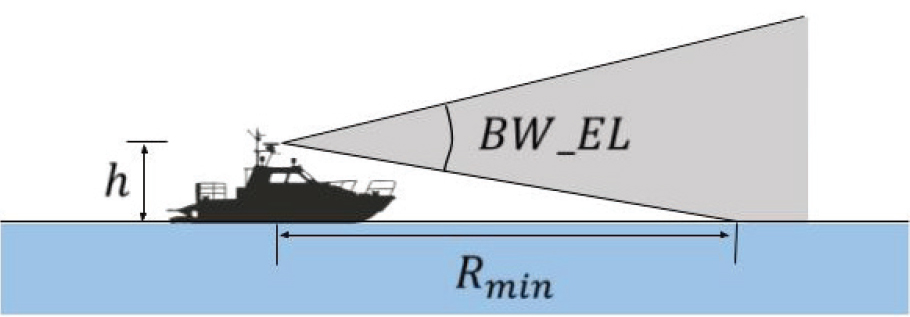
MVRs are typically mounted at high locations on vessels to achieve an unobstructed view of the surrounding scene, such as the top of the wheelhouse or on a mast. Instead of the theoretical maximum range of a radar supplied by the vendor (which depends on the transmit power and the antenna gain, among other parameters), the common limit to the practical, maximum range for target detection is the height of the radar and the height of the target from the sea surface. An approximate formula to estimate the maximum radar horizon due to the Earth’s curvature (Skolnik, 1990) is ![]() , where Rmax is the maximum range (in nautical miles [nmi]), h is the height of the radar (in feet), and H is the height of the target (in feet). For example, an MVR mounted at a height of 20 feet above water can see a surface target out to 5.5 nmi (or a 20-foot-high boat out to 11 nmi). The mounting height of the MVR will also impact its minimum range for detection due to the elevation beamwidth, BW_EL, of the radar (Figure 2.1). This is given approximately by Rmin=h/tan(BW_EL/2). For example, an MVR with BW_EL=25 degrees mounted at h=20 feet above the sea surface would have difficulty seeing a target closer than Rmin=90 feet. Therefore, there is a compromise between the maximum and the minimum range—raising the radar in order to see a distant target will also sacrifice its ability to see close-in targets. Moreover, a higher antenna position will lead to larger sea clutter returns and the range over which they are detected. All of these tradeoffs need to be taken into consideration when choosing a proper antenna height.
, where Rmax is the maximum range (in nautical miles [nmi]), h is the height of the radar (in feet), and H is the height of the target (in feet). For example, an MVR mounted at a height of 20 feet above water can see a surface target out to 5.5 nmi (or a 20-foot-high boat out to 11 nmi). The mounting height of the MVR will also impact its minimum range for detection due to the elevation beamwidth, BW_EL, of the radar (Figure 2.1). This is given approximately by Rmin=h/tan(BW_EL/2). For example, an MVR with BW_EL=25 degrees mounted at h=20 feet above the sea surface would have difficulty seeing a target closer than Rmin=90 feet. Therefore, there is a compromise between the maximum and the minimum range—raising the radar in order to see a distant target will also sacrifice its ability to see close-in targets. Moreover, a higher antenna position will lead to larger sea clutter returns and the range over which they are detected. All of these tradeoffs need to be taken into consideration when choosing a proper antenna height.
In addition to the height of antenna placement, having an unobstructed view from the antenna of the surrounding environment is also important to the quality of radar returns. When MVRs are mounted on vessels, other close-by structures such as masts, stanchions, and funnels can cause blockage and spurious echoes. These structures lead to deleterious phenomena, including (1) blind sectors in which the radar experiences complete blockage, (2) shadow sectors in which the radar can still see targets at longer range but the antenna pattern has a degraded beam and/or higher sidelobes,
and (3) spurious echoes from large objects in other directions due to multiple scattering from onboard obstructions. While these effects are well known and often explicitly mentioned in MVR operator’s manuals,15 MVRs are nonetheless mounted in the midst of topside obstructions due to practical space constraints. During the 2007 Kentish Flats trial in the United Kingdom, Marico Marine (on behalf of the British Wind Energy Association) identified shipboard radar mounting issues to be a main cause of spurious echoes from offshore wind turbines (Marico Marine, 2007). This will be discussed further in the section on WTG impacts on MVR at the end of this chapter.
OFFSHORE WIND TURBINE GENERATOR CHARACTERISTICS AND DEPLOYMENT
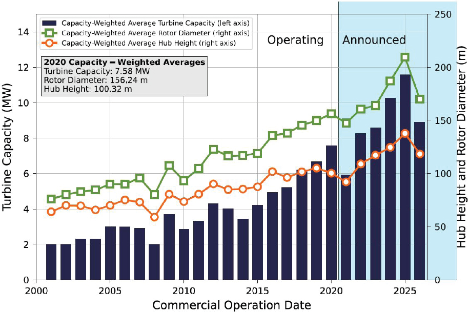
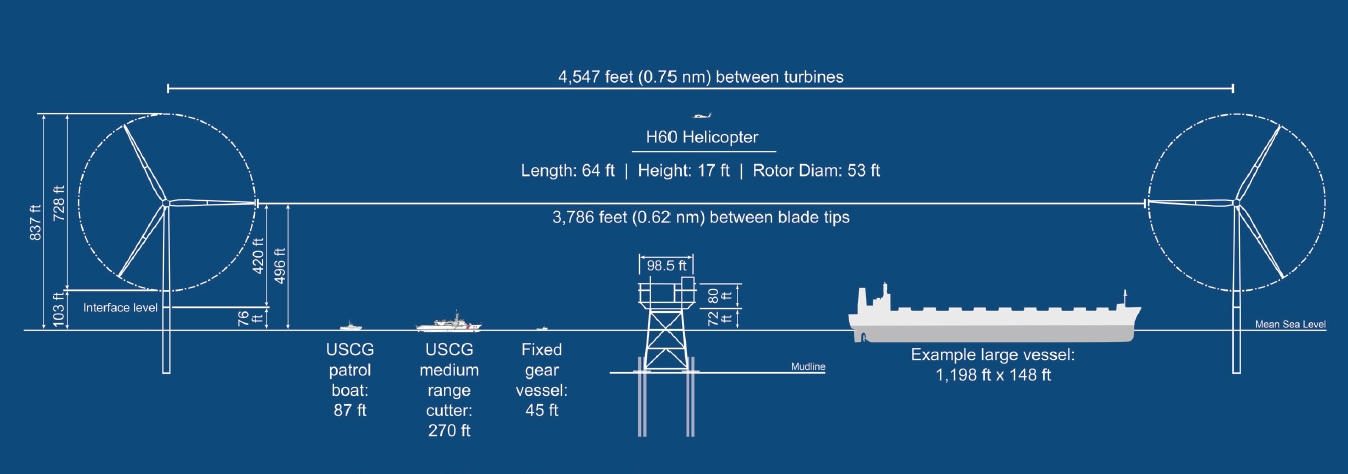
The standard design for offshore WTGs—three-bladed, upwind, horizontal axis—is the same as that for onshore WTGs. However, because offshore wind turbines do not have the same transportation infrastructure limitations of onshore wind turbines where blade size is limited (e.g., by the roads that trucks can take and the radius of the turns, and the capacity of the cranes used in construction), they tend to be relatively larger machines (Hartman, 2021). Figure 2.2 illustrates the global trend to increase both the hub height of the turbine and the rotor diameter. To date, the offshore wind developers that have submitted a Construction and Operations Plan (COP) with the Bureau of Ocean Energy Management (BOEM) all indicate that they are considering WTGs with hub heights above 450 feet (137 meters [m]) and rotor diameters greater than 700 feet (213 m), with the maximum of 525-foot (160 m) hub height and 853-foot (260 m) rotor diameter (BOEM, 2021).
These offshore machines are designed using the same materials as the onshore WTGs for the tower, nacelle, and blades. The towers are tubular structures that are typically tapered toward the top and are constructed from steel. The idea of constructing WTGs with concrete towers has been around for some time, with renewed interest in its use for offshore WTGs. Spain’s ELICAN Project recently deployed a 5-megawatt (MW) offshore WTG with a concrete tower. This change in construction material will impact the large radar cross section (RCS) of WTGs, likely leading
___________________
15 For example, see manuals provided by Furuno USA at https://www.furunousa.com/en.
to a reduction as compared with those that have steel towers. However, more radar modeling, data collection, and verification are needed.16
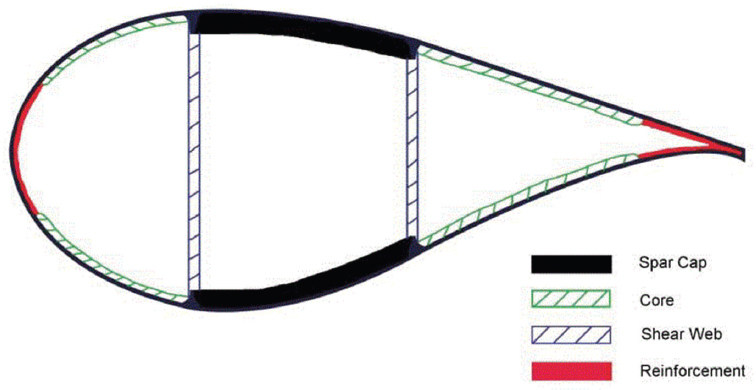
The design of wind turbine blades is a topic of much research (Marlay et al., 2020), with the ultimate goal to capture as much energy from the wind as possible while taking into consideration operating criteria such as extreme loading, material fatigue, tip deflection, and weight and cost. Blades are made from a combination of lightweight wood (usually balsa), fiberglass, and, now more commonly, carbon fiber (Figure 2.3). These materials provide the required stiffness-to-weight ratio. WTGs are also commonly equipped with systems to protect sensitive and costly electrical equipment in the event of a lightning strike. WTG blades often have lightning receptors embedded in the surface of the blade, which are connected via a metal cable to the hub of the WTG and then down to ground (Crocker, 2020).
The nacelle of a WTG sits atop of the tower and houses components such as the generator and gearbox, if used. The nacelle cover functions to protect these components from the elements and is typically constructed from a fiberglass composite to reduce the weight of the nacelle.
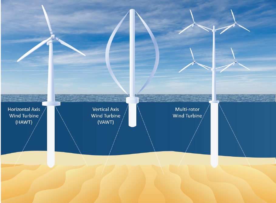
There are also more novel offshore WTG designs being explored in the United States from vertical axis wind turbines (VAWTs) to designs consisting of multiple turbines deployed on a single tower (Figure 2.4). VAWTs may hold promise for the offshore environment owing to their insensitivity to the wind direction and the lower center of gravity of the machines, with the generator and gearbox located at the base of the turbine rather than housed at the top of the tower. However, these designs are yet to be proven economical and are still in the research and development phase. For this reason, the committee has focused this report on the impacts from the standard three-blade,
___________________
upwind WTGs. If research and development leads to a lower levelized cost of energy for other WTG designs, this may warrant new research on the electromagnetic signatures and the impact of those new WTGs on MVR.
Offshore WTGs can also employ many different substructure foundations. The substructure type is largely dependent on the water depth at the WTG location. Fixed-bottom monopile foundations are the dominant technology for the proposed offshore WTG installation for the eastern United States (Musial et al., 2021). This is in part because of the shallower waters on the Outer Continental Shelf off the East Coast of the United States and because it is a mature technology. This may change for fixed-bottom foundations where jacketed or gravity-based foundations may become more prevalent. As the offshore market develops further and projects proposed off the West Coast of the United States and in other areas such as the Gulf of Maine, the Gulf of Mexico, the Great Lakes, and farther off the Atlantic Coast move forward, it is likely that other floating foundation types will be employed, such as the semisubmersible substructure. Whereas fixed-bottom substructures such as monopiles are fixed to the sea floor providing a rigid tower, a floating foundation WTG has added complexity for MVRs due to the sea state, which can induce heave, yaw, surge, roll, sway, and pitch (Figure 2.5). These floating WTGs can have translational movements (surge, sway, and heave) and may not always remain at the same position, moving 20–50 m around a center point, depending on the design of the mooring of the WTG. The floating WTGs will be designed to minimize the vertical (heave) and the rotational (roll, pitch, and yaw) movements of the platform.
Without terrain features that are present onshore, offshore wind farm developers can arrange the WTGs in a standard grid pattern. Data from BOEM show that a typical layout for a single offshore wind farm within the lease areas off the East Coast of the United States will include turbines spaced approximately 1 nmi × 1 nmi (BOEM, 2021). This distance between WTGs and the orientation of the WTG arrangement within an offshore wind farm may vary from developer to developer (e.g., Figure 2.6), but a regular grid arrangement can be expected. There has been some research into optimizing the micro-siting of WTGs in wind farm layouts (i.e., the distance and angle between one WTG and the next relative to the predominant wind direction) to reduce the wake effects created by upwind turbines on downwind turbines, which can lead to decreased wind speed and decreased power output (Hou et al., 2019). However, given the focus of this study to examine MVRs, which by their nature are moving relative to the WTGs (save for the spacing between the WTGs, which will be discussed in later sections), the orientation of the grid pattern of WTGs in an
offshore wind farm is irrelevant. This statement may not be true for other land-based radar types used for air surveillance purposes or for HF radar systems used to track ocean currents, which are beyond the scope of this study.
With offshore wind farms expected to be designed in a grid pattern, the number of turbines expected for a given project will be dependent upon the size of the offshore lease areas and the distances between WTG rows and columns in the layout, as well as other factors such as the power offtake agreements to the grid, the capacity of the interconnection transmission lines, and the power rating of the WTGs. The data from the COPs submitted by developers to BOEM show projects ranging from 15 WTGs to 174 WTGs per project (BOEM, 2021).
ELECTROMAGNETIC CHARACTERISTICS OF WIND TURBINE GENERATORS
The electromagnetic characteristics of WTGs relevant to MVR are related to their geometries and their material compositions. The largest component of the WTG is the tower, which is nominally constructed of steel to provide structural strength. Since the steel is electromagnetically conductive, the tower is the main source of MVR returns. This is because its physical extent makes it extremely electrically large compared to the operating wavelength of the MVR, thereby creating a

very strong radar return. The nacelle is a smaller and more complex mechanical structure, housing the generator and gearbox for the WTG, housed in a fiberglass enclosure to protect the machinery from the elements. The fiberglass enclosure is non-conducting and will allow incoming radar signals to pass through it, while the inner metallic machinery presents a complex electromagnetic scattering profile. Any radar signals that penetrate the fiberglass enclosure will largely be scattered incoherently and not reflected back to the radar source, which translates to a much lower effective RCS than that of the tower, where RCS is a measure of the strength of the backscattered signal from a target to the radar and has units of square meters (specifically, the product of incident power and RCS yields the power of the signal reflected back to the radar). The wind turbine blades are commonly composed of lightweight materials engineered to provide mechanical robustness while capturing wind energy efficiently. These materials may include wood, fiberglass, and carbon fiber composites. The complex dielectric permittivity of these materials determines how well each material absorbs and reflects incoming electromagnetic waves; therefore, the blade composition, construction, and position during operation all affect the degree to which the blades contribute to the WTG’s overall RCS. It should be noted that the frequency of the radar has a strong influence on the reflectivity of the blade surface. For example, it has been reported that the lightning protection cable inside the
blade can be a dominant contributor to the blade return in the HF band (3–30 megahertz) (Crocker, 2020). However, this is not the case at MVR frequencies, as radar imaging measurements carried out on a utility-class wind turbine (Li et al., 2016) clearly showed that the exterior of the blade gave rise to the dominant radar signature in the frequency range 3.1–5.3 GHz.
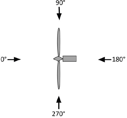
When evaluating the total RCS of a turbine, a coordinate system is centered on the turbine viewed from above, with 0 degrees designated as the direction of the front broadside view of the turbine (Figure 2.7). The RCS of a single horizontal axis turbine, dominantly a result of the tower, can be as high as 40 decibels relative to a square meter (dBsm) at S-band frequencies and 45 dBsm at X-band frequencies (Kent et al., 2008) when measured in the electromagnetic near field defined by a range closer than (2L2)/λ, where L is the tower height and λ is the radar wavelength. The nacelle’s RCS is maximum mainly in the 90-degree and 270-degree directions but is considerably lower than that of the tower. Maximum blade RCS occurs in the 0-degree and 180-degree directions, with Doppler signatures arising from blade rotations (blade flashes) that are maximized in the edge-on radar views (90 degrees and 270 degrees). Blade rotation creates a time-varying Doppler signature depending on the speed of rotation of the blades as well as the shape and position of the blades (Naqvi et al., 2010).
Past efforts to characterize the RCS of WTGs have led to a thorough understanding of the electromagnetic scattering phenomenology of WTGs. For instance, the Air Force Research Laboratory (AFRL) conducted a comprehensive measurement campaign in 2006 on a land-based wind farm in Fenner, New York (Buterbaugh et al., 2007; Kent et al., 2008). Dynamic radar signatures were collected on a number of 1.5-MW WTGs with a tower height of 65 m and a blade length of 34 m. Subsequently, simulation results were generated by applying the ray-tracing code XPATCH (Hazlett et al., 1995) to a high-fidelity computer-aided design model and compared with the measurement data, thus establishing a level of confidence on the use of simulation tools for predicting WTG signatures.
The anticipated offshore wind facilities in the United States over the next 15 years are considerably larger than those at Fenner, New York, with tower heights ranging from 135 m to 158 m and blade lengths ranging from 105 m to 128 m. Therefore, it is natural to ask how the RCS of these larger turbines will scale and whether they may pose a greater challenge to the operation of MVRs. While it is possible to simulate the RCS of these larger structures to provide turbine-specific data,
some general observations can be made based on our current understanding of the WTG scattering physics.
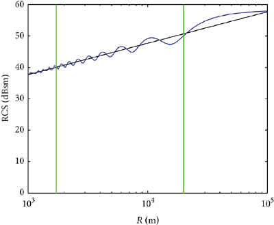
First, based on the physical-optics theory, it is expected that the RCS of a turbine tower will scale linearly as a function of its diameter and quadratically as a function of its height. This means doubling the tower diameter and the tower height will lead to a 2(22) = eight-fold (or 9 dB) increase in RCS (Figure 2.8A). However, in scenarios where the MVR is operating sufficiently close to or even inside the wind farm, several research groups have argued that a taller tower may not give rise to the high level of RCS predicted under the standard far-field condition. This argument, first discussed in Van Lil et al. (2009) and later explored in greater detail in Grande et al. (2014), is that the large RCS predicted by physical optics is due to the constructive interference achieved along the entire length of the tower. However, when the radar is in the near-field region of the tower (as defined by a range closer than (2L2)/λ), the portion of the tower farther from the radar does not contribute to the RCS (Figure 2.8B). Therefore, the expected RCS under such conditions is considerably less than the far-field RCS. Figure 2.9 shows that the RCS in this region is independent of the height of the tower and actually decreases as the radar gets closer to the turbine. It is expected that most MVR encounters with WTGs fall within this region. Therefore, the actual RCS experienced by an MVR will be much less than that predicted under the far-field condition.
Second, the turbine blade RCS will likely exhibit the same kind of near-field effect as the tower. A “blade flash” is typically observed in the far field when the blade becomes perpendicular to the radar line of sight. When this occurs, all the points along the blade add coherently in phase. However, if the blade is too long for the radar to be in its far field, near-field phasing effects will limit the region of the blade that contributes to the flash. As the blade continues to rotate, the region moves along the blade and creates a diffused flash in time. In other words, a longer blade does not lead to a stronger flash, but a more extended flash, in the near field. This phenomenon has been observed in field measurements in Li et al. (2016). Additionally, the rotating blades give rise to a time-varying RCS and a corresponding Doppler signature. Even though longer blade lengths are planned for future WTGs, the maximum tip speed of turbine blades is not expected to exceed ~100 m per second (Ennis, 2021). Therefore, the maximum Doppler frequencies are expected to top out at 6.3 kilohertz (kHz) at X-band and 2 kHz at S-band.

Third, larger spacing between turbines will lead to less electromagnetic interaction between turbines. Consequently, it is expected that spurious echoes due to multiple scattering between turbines will lessen as turbine spacing increases. During the 2007 Kentish Flats trial (Marico Marine, 2007), multipath echoes attributable to turbine–turbine scattering were sometimes observed. In that case, the turbine spacing was approximately 0.38 nmi. For larger turbine spacing, spurious echoes due to multiple scattering between turbines will be less prominent.
To summarize, simulation tools exist that can accurately characterize the RCS of larger turbines to be deployed in the next 15 years. Without carrying out such detailed simulation, it can be argued, based on the academic community’s current understanding of the electromagnetic scattering characteristics of WTGs, that (1) the RCS of larger WTGs may not scale up as drastically as one may expect from the standard far-field physical optics theory due to near-field phasing effects, (2) the Doppler signature due to longer blades will stay bounded owing to the anticipated limit on blade tip speed, and (3) multiple interactions between WTGs may lessen due to the larger planned spacing between WTGs.
WIND TURBINE GENERATOR IMPACTS ON MARINE VESSEL RADAR
The impact of WTGs on MVR performance is influenced by a number of factors, such as the following:
- MVR design choices, including operating frequency, antenna characteristics, transmitter type, receive processing approach, and ARPA design.
- Characteristics of the WTG deployment, including the RCS of the WTG’s constituent components; size and separation of the WTGs; extent of the WTG farm; and blade size, composition, orientation, and tip speed.
- The operating environment, including target RCS, radial velocity, spatial distribution, and course; propagation characteristics, such as anomalous propagation due to ducting, shadowing, and multipath; and sea state affecting clutter signal strength and spectral distribution.
As described above, MVRs typically operate within two distinct frequency bands, depending on vessel size. Larger vessels commonly use S-band (in the vicinity of 3 GHz) systems, as this frequency provides better propagation characteristics in adverse weather. Smaller vessels favor X-band (9.4 GHz), as antenna gain—proportional to effective area divided by wavelength-squared—improves for the smaller antenna sizes operating at higher operating frequency. The MVR antenna design incorporates narrow azimuth beamwidth (typically of 1–2 degrees) and very broad elevation patterns (around 20–30 degrees) to compensate for vessel pitch and roll (Acland, 2021; Haynes, 2021; Kunz, 2021). Additionally, the majority of fielded MVRs employ a magnetron-based transmitter and corresponding non-coherent signal processing receive chain. Solid-state transmitters are gaining in popularity, providing better reliability and reduced operating costs; solid-state transmitters provide stable frequency operation, thereby enabling coherent Doppler signal processing on receive. It is currently estimated that roughly 80–90 percent of MVRs are magnetron-based (Haynes, 2021), with the expectation that 50 percent of new MVR sales will be solid state in the future (Acland, 2021; Haynes, 2021; Kunz, 2021).
Magnetron-Based Radar
In the case of magnetron-based MVR, the radar transmits and receives a pulse at the specified operating frequency for a given azimuth. The antenna rotates with typical rates of 24–45 revolutions per minute (Acland, 2021; Haynes, 2021; Kunz, 2021). Range resolution equals the speed of light times the pulse width divided by two, where pulse width is variable and depends on the operating environment. Objects at differing, resolvable ranges experience a time delay from the moment of transmission nominally equal to twice the distance from the radar to the object divided by the speed of light. A processor compares the strength of the received pulses at a given angle and range to an operator selectable threshold (inversely related to receive gain identified in earlier sections); returns that cross the threshold are declared targets. The strength of the return is proportional to the RCS of the reflective object divided by range to the fourth power. While published values for the RCS of a marine WTG vary, sensible numbers are approximately 40 dBsm at S-band and 45 dBsm at X-band, with the RCS of the blades changing as a function of aspect with respect to the nacelle and representing the dominant component of the return from the frontal aspect (Danoon and Brown, 2013; Ling et al., 2013; Hao Ling, personal communication, 2021). In a magnetron-based radar, the composite RCS influencing the strength of the echo return is the result of the complex interaction of all the components of the WTG, where the return from the tower generally dominates for most aspect angles. By way of comparison, the RCS of a small boat is on the order of 0 dBsm, whereas a medium-size ship has an RCS of roughly 40 dBsm, and a larger shipping vessel can have an RCS approaching 60 dBsm (Williams et al., 1978; Nathanson, 1999). Thus, the strength of the return pulse from the WTG is significant and can be about the same as that from a medium-size ship. This means that the radar display of returns over range and angle, referred to as the PPI, is cluttered with WTG returns in the absence of mitigating techniques.
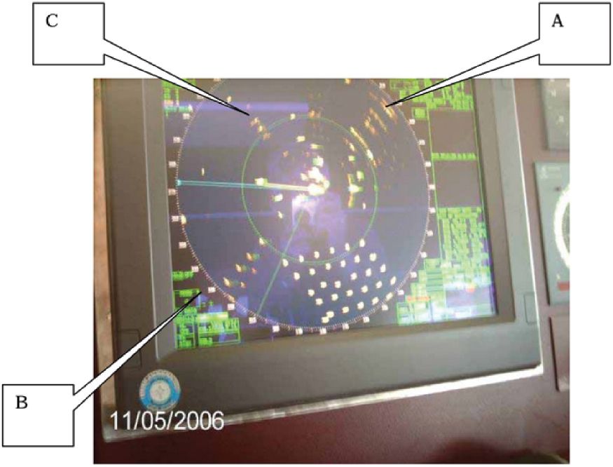
Figure 2.10 shows an illustrative example of a PPI for magnetron-based MVR operating in the vicinity of the Kentish Flats Offshore Wind Farm. As seen from the captured PPI display, there are numerous returns from the WTG farm, including the anomalous returns designated by indicators A, B, and C, as well as the regular grid of returns in the lower right part of the display. A number of phenomena complicate a detailed understanding of this PPI display, including multipath between the vessel and radar, as well as sidelobe antenna effects.
Radar detection typically involves binary hypothesis testing (Skolnik, 1980): the radar must determine which of two models—the null hypothesis or the alternative hypothesis—led to the observation. The null hypothesis is the case of additive interference plus noise, indicating no target. Interference essentially is anything that is not the sought-after target, leading to an important
adage in radar: one person’s clutter is another’s target (Richards, 2005). In contrast, the alternative hypothesis is the case of target plus interference and noise. Different radar designs and modes are capable of distinguishing desired from undesired objects with a high degree of efficacy, depending on the complexity of the system.
Oftentimes, the radar threshold is set algorithmically to meet a desired probability of false alarm—the probability of choosing the alternative hypothesis when no target is present—while maximizing probability of detection (Levanon, 1988). In the case of MVR, the processor simply applies a detection threshold to the receive pulse, which if crossed, leads to the declaration of a target at that range and angle position. For this reason, the typical MVR design appears much more reliant on operator control of the threshold setting than, for example, radar systems used for air traffic control or military applications.
Given the copious detections shown on the MVR display in Figure 2.10, a natural operator response is to adjust the detection threshold upward (reduce the receive gain) to “declutter” the PPI. Unfortunately, the unintended consequence of an increased detection threshold is the suppression of weaker returns from smaller vessels or objects, such as buoys, that “fall under” the detection threshold setting. This undesirable consequence was acknowledged by MVR manufacturers, who further indicated that small vessels were primarily the domain of coast guards, navies, and search and rescue (SAR) operators. Moreover, in the context of navigation, it was suggested that smaller boats could easily maneuver out of the way of larger ships. Such statements are concerning,
however, as the complexities of multiple ships traversing a large WTG farm may complicate the perceived ease with which small craft can maneuver from harm’s way, or the corresponding impact on other vessels responding to attempts to navigate free of collision.
Other factors complicate the interaction between radar and WTG, including propagation-specific effects. Own vessel multipath is a significant concern (Haynes, 2021; Kunz, 2021). Specifically, the coupling between flat plate and modestly curved surfaces on the vessel and the radar leads to WTG detections appearing to come from ambiguous angles. In an environment with a dense population of WTGs, the many ambiguous returns on the PPI hold the potential to confuse operator interpretation of the environment. Additionally, these ambiguous returns will affect the ARPA and calculations of CPA and TCPA, since multipath yields false range and angle information and can affect tracking of more relevant targets.
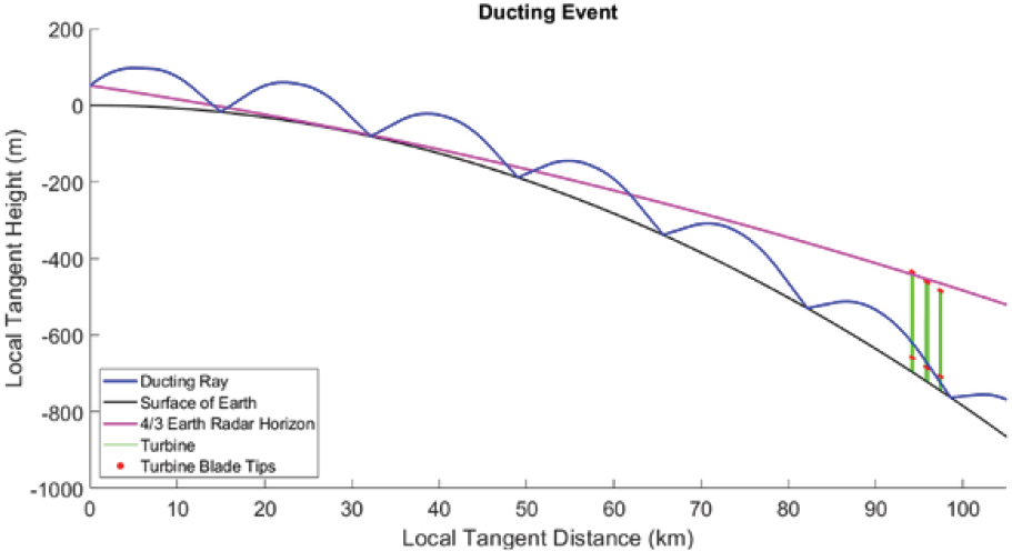
Ducting is an anomalous propagation mode, whereby temperature inversion layers in the atmosphere result in stratified changes in the index of refraction and a corresponding waveguide effect. It occurs more commonly in marine and humid environments. Ducting can be a concern when interpreting radar returns, as the radar operating range extends beyond normal prediction. In the case of ducting, WTGs at long range can ambiguously enter the radar receive window and be mapped to closer, unambiguous ranges, thereby complicating the operator’s understanding of the environment (Colburn et al., 2020; Colburn, 2021). Figure 2.11 depicts the impact of ducting on the radar’s field of view. Specifically, ducting allows the radar to see the entirety of WTGs that normally appear beyond the radar line of sight (LOS) using the standard 4/3 Earth model. Ducting increases at lower operating frequencies. Additionally, the MVR’s broad elevation pattern, used to mitigate vessel pitch and roll, exacerbates the ducting problem, as it provides high gain illumination out to the radar horizon. Figure 2.11 further suggests that MVR will see distant tops of WTG farms even under normal propagation conditions. The likely result is the inclusion of additional returns cluttering the PPI display.
Shadowing occurs when an object impedes the LOS between the MVR and other objects further in range. Depending on the orientation among radar, target, and turbine layout, WTGs can mask radar contact during the course of a target’s trajectory. Targets lost in shadow do not appear on the PPI, nor figure into the ARPA calculations leading to CPA and TCPA. Figure 2.12 shows a transmission simulation of a 3-GHz radar within a 3 × 3 grid of WTGs with 3.3-m diameter towers; the streaks running from the lower left to upper right have null depths of ~6 dB and represent the shadowing effect. The radar’s ability to detect targets passing through a shadow is diminished, but the shadows are very narrow. For the more likely case of larger diameter WTGs and a larger farm, the study committee expects shadowing effects to worsen. However, shadowing is a lower order effect on the MVR in comparison with other factors, such as strong reflections from the WTG tower and ambiguous multipath returns.
Operation within the WTG farm will lead to additional effects on the MVR. Notably, within the WTG farm, concerns include receiver saturation due to large reflections from nearby objects; a highly complex multipath environment, including energy reflected from one WTG to another, and target returns reflecting from WTGs; and diversity of viewing angles to WTG blades leading to spatial variation in the WTG RCS.
At close range, the strength of the return echo may saturate the receiver amplifiers and exceed the dynamic range of the digitization stage, leading to distortion of the receive signal and further suppression of weaker targets. Distortion includes signal harmonics that degrade the radar scene with additional, spurious signals.

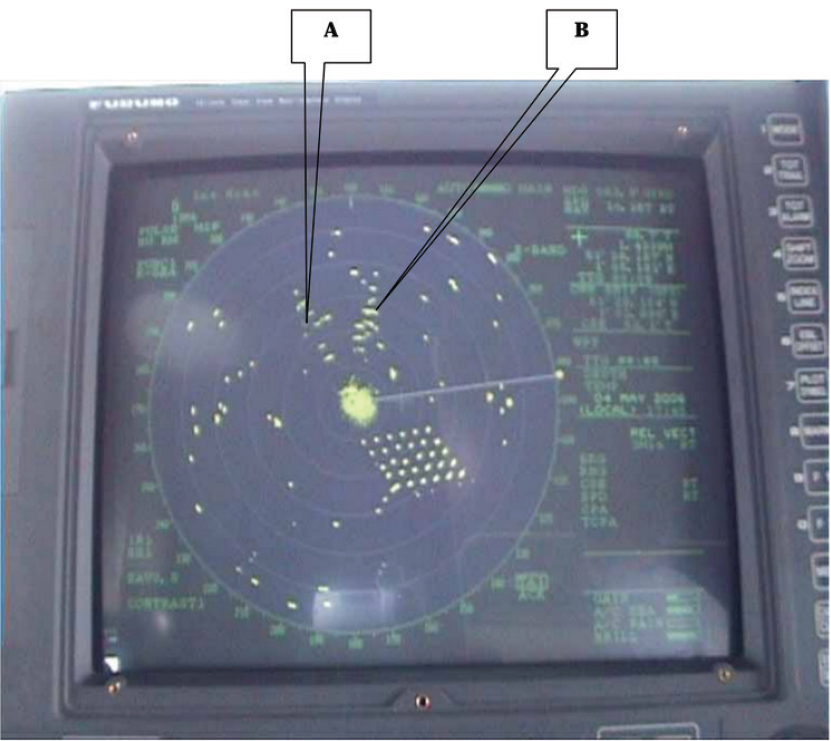
Multipath within the WTG farm can lead to additional echoes from a given WTG, with the multipath signal occurring at a later range. Multipath echoes contaminate additional range bins, appearing on the PPI as a multiplicity of anomalous detections, and can result from interactions with passing vessels, as shown in Figure 2.13; indicator A represents reflections from the Shivering Sands Towers, whereas indicator B identifies multipath reflections from a large vessel with flat sides.
The RCS of the WTG blades is highly dependent on the aspect between the radar and the WTG nacelle, assuming a horizontal axis wind turbine, so as the vessel traverses the WTG farm, the performance of the MVR will vary dynamically and create a complex PPI display for operator interpretation. Figure 2.14 shows the variation of RCS for the case of smaller, land-based WTGs with 34-m blades and a 65-m tower; the RCS of the land-based WTGs is roughly 20–25 dB smaller than their marine-based variants since RCS is inversely proportional to wavelength and proportional to the square of the tower height times the tower diameter (Hao Ling, personal communication, 2021). The red lines in Figure 2.14 correspond to measurements under the AFRL Fenner data collection program, and the blue lines are simulated using a highly validated, computational electromagnetics code called XPATCH (Hazlett et al., 1995). The left-most panel in Figure 2.14 is shown for 1.5 GHz and the frontal incidence, so the response is relatively constant, whereas the right-most panel of Figure 2.14 is at 3.6 GHz and 137 degrees from frontal incidence, so that RCS varies substantially
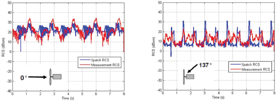
as the blade rotates. At X-band, the RCS will increase by roughly two orders of magnitude over the L-band result. The larger size of marine WTGs will also result in larger RCS values in general. The radar will commonly be in the near field of the WTG, resulting in variability in the effective RCS of the WTG. Thus, as previously stated, expected values for WTG RCS are approximately 40 dBsm at S-band and 45 dBsm at X-band.
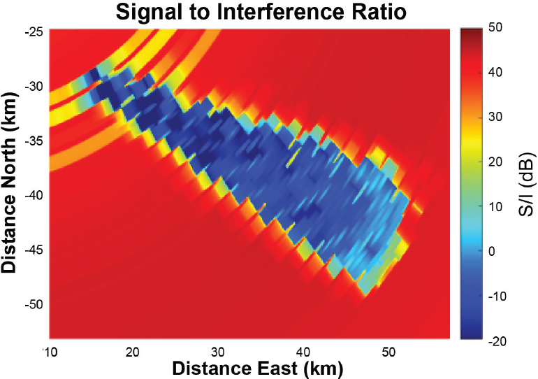
A detailed assessment concerning the impact of WTGs on MVR requires, in part, physics-based modeling, simulation, and analysis combined with collection and interpretation of field test data anchoring the simulation software. An example for a simulated land-based radar operating in the presence of WTG interference was shared in a presentation to the committee (Figure 2.15). Using WINDTRX, which combines a highly validated U.S. Department of Defense radar model called ESAMS with a scatter-based model for a WTG, Figure 2.15 shows an example of signal-to-interference ratio (S/I) for a Federal Aviation Administration ASR-9 situated at the John F. Kennedy International Airport for a 0 dBsm target (Colburn et al., 2020; Colburn, 2021). The ASR-9 is a solid-state radar employing clutter suppression and Doppler filtering (Taylor and Brunins, 1985). While this scenario corresponds to a land-based, solid-state radar, the impact of the WTG on performance is evident and cautionary for MVR. Specifically, the region of low S/I (shaded blue in Figure 2.15) in the southeasterly direction is attributed to the unmitigated impact of WTGs on radar performance. In general, reliable detection requires an S/I of approximately 13 dB, so the region shown in blue in Figure 2.15 represents substantial degradation in detection capability, with expected detection rates of less than a few percent for returns from objects other than WTGs with RCS values less than 20 dBsm, and only ~25 percent for an object with RCS of approximately 30 dBsm. In the context of MVR, Figure 2.15 confirms that WTGs are significant sources of interference to detecting moving targets and smaller stationary objects, such as navigation buoys. To reiterate, this example does not apply bespoke methods to mitigate WTG interference possible with solid-state radar technology, a topic considered subsequently in the context of MVR.
Doppler-Based Solid-State Radar
Solid-state radar was primarily introduced by MVR manufacturers for reliability improvements over magnetron-based systems. Solid-state radar provides a stable local oscillator, a prerequisite for pulse compression and Doppler processing, or what is commonly referred to as coherent radar
signal processing. The terms “Doppler-based radar” and “solid-state radar” are used interchangeably in this section and throughout the remainder of the report. Pulse compression allows the radar to transmit energy over a long, coded pulse while achieving the resolution of a short pulse (Melvin and Scheer, 2012). Doppler processing further enables the radar to aggregate target reflected energy over multiple pulses, thereby increasing signal-to-noise ratio (SNR), and further allows separation of signal reflections with different range-rates relative to the radar LOS. The corresponding range-rate is a result of the combined motion of both the radar and the object under illumination, so even stationary objects—such as coastlines, bridges, and buoys—will have a non-zero Doppler shift depending on their angle relative to the marine vessel’s velocity vector.
Radar manufacturers increasingly offer solid-state radar with Doppler processing to their patrons (Acland, 2021; Haynes, 2021; Kunz, 2021). With Doppler processing, the radar can instantaneously determine whether a target is approaching or receding, and how quickly. Additionally, each Doppler filter has an angular beamwidth for stationary objects, which gets finer with longer dwells; this enables Doppler-based radar to more finely map out coastlines, docks, underpasses, etc. Conversely, Doppler-based radar can separate returns from stationary objects and moving objects, thereby improving the radar sensitivity to moving targets and smaller stationary objects since each target return only competes with the RCS of those returns within its Doppler filter, as opposed to magnetron-based radar where the target competes with the aggregate sum of all reflections within the range bin of interest.
With the aforementioned in mind, the WTG impacts solid-state radar similarly to the magnetron-based radar systems, with the distinction that solid-state radar can separate objects by Doppler frequency. Stationary objects, such as the WTG tower or a buoy, appear at a fixed Doppler depending on the angle between the object location and the marine vessel direction of motion. Thus, WTG towers at different angles will have different Doppler shifts. Reflections from the WTG blades will
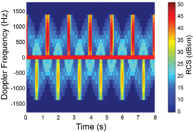
generally yield returns over a continuum of Doppler frequencies, depending on the orientation of the radar to the blade motion. Figure 2.16 shows the simulated spectrum for a nominal WTG and an orientation where the blades appear to rotate toward the radar given the spread of the Doppler response (Colburn, 2021). The Doppler returns from the blades can lead the radar to determine the presence of approaching and receding targets (Haynes, 2021; Kunz, 2021). With many WTGs in the radar field of view, the operator will have to contend with a potentially confusing radar picture if relying on Doppler information and absent any mitigation strategies.
A detailed description of how WTGs manifest in Doppler-based radar is given in Figure 2.17. Panel A of Figure 2.17 shows the geometry among a vessel with MVR, regularly spaced WTGs, and two moving targets. As seen, target T1 approaches the port side of the vessel carrying the MVR, whereas starboard target T2 moves away from the radar in the cross-track direction. Panel B of Figure 2.17 plots Doppler frequency versus the change in angle measured 90 degrees clockwise from the MVR’s velocity vector (so, 0 degrees is nominally port side). This convention is chosen to place stationary objects orthogonal to the MVR’s velocity vector at 0 Hertz Doppler and is often called the sidelooking radar case. Target T1 appears in the vicinity of 80 degrees, with the chosen convention that approaching targets are given positive Doppler frequency. Target T2, near 100 degrees, shows a Doppler frequency that is the result of the combined motion of both vessels; assuming both vessels move with similar velocities, the MVR appears to approach target T2, yielding a positive Doppler lower in frequency than target T1. It is important to note that Panel B shows the angle and Doppler response of targets and WTGs from different ranges; in practice, the radar further separates objects at different ranges based on time difference of arrival.
The Doppler frequency of a stationary object is strictly a function of angle between the MVR and the non-moving object; objects orthogonal to the velocity vector (at a change in angle of 0 degrees, 180 degrees, and –180 degrees) have zero Doppler, as there is zero range-rate with respect to the MVR. Stationary objects near the bow or stern, at 90 degrees or –90 degrees, approach with maximum positive and negative Doppler relative to other non-moving objects, as the radar moves with highest or lowest range-rate relative to these points. All other objects fall along the sinusoidal curve shown in Figure 2.17, as the Doppler is strictly given as twice the projection of the MVR’s velocity vector onto a unit vector pointing toward the object of interest divided by the radar
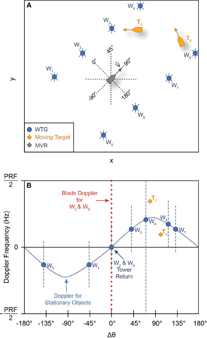
operating wavelength (Richards, 2005). In the absence of multipath reflections, the returns from the wind farm towers fall on the sinusoidal line, and any Doppler due to blade motion will extend off of the sinusoidal stationary return line. Thus, the blade Doppler falling off of the sinusoidal line will compete with returns from moving targets and can mask detection of smaller vessels. The differences in the vertical dashed lines corresponding to WTG Doppler suggest different amounts of Doppler spread based on orientation between radar and nacelle.
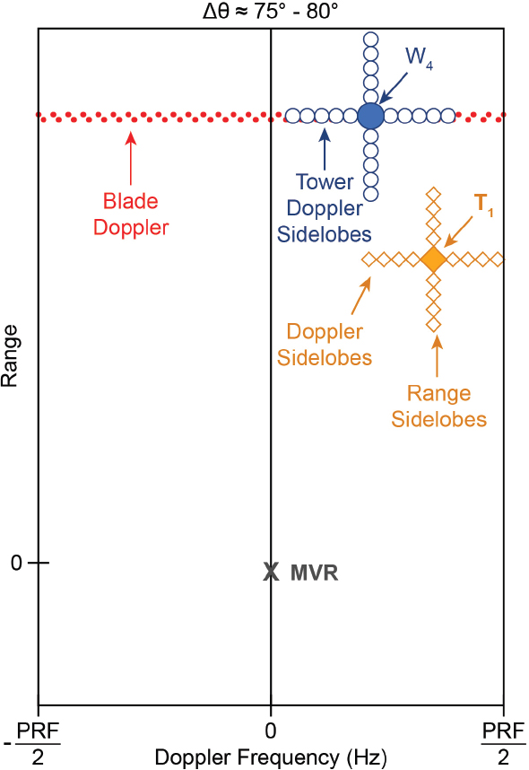
Range-Doppler sidelobes are another unique aspect of solid-state radar relative to its magnetron-based counterpart. Solid-state radar enables increased duty cycle waveforms yet achieves the resolution of short pulses using a matched filtering method colloquially called pulse compression. The range response of a standard linear frequency modulated waveform is a sinc (sin(x)/x) pattern, exhibiting a mainlobe and, depending on the weighting function, a sidelobe response that is nominally 40–60 dB below the mainlobe peak in the near sidelobe region, further diminishing away from the peak. As a result, a WTG may yield sidelobes in range appearing as additional detections or interference to weaker targets. A similar effect occurs with Doppler processing, where the radar coherently integrates multiple pulses to achieve the SNR of a longer pulse, and the resulting Doppler sidelobes for WTGs may appear as additional detections or can mask weaker targets in the absence of tailored signal processing methods. It is important to point out, however, that all of the energy returned from a WTG in magnetron-based radar competes with the target at that same range, whereas coherent range-Doppler processing generally minimizes those challenges so that primarily the weaker interference signal within the same range-Doppler cell competes with the target of interest. Figure 2.18 illustrates the range-Doppler response for a target and WTG, depicting each object’s range-Doppler response, including the two-dimensional sidelobe response extending over the range-Doppler map. In comparison to Figure 2.16, the Doppler spread of the WTGs is variable over range due to changes in aspect between MVR and WTG nacelle. Additionally, Figure 2.16 does not depict the Doppler sidelobe responses, which spill off of the sinusoidal response in the vertical direction absent any mitigation.
The impact of WTG on solid-state radar requires further assessment, as the majority of fielded radar, and hence collected data on WTG impacts, are magnetron-based. The well-known Kentish Flats Wind Farm results, for instance, correspond to a magnetron-based radar (Marico Marine, 2007). As reliability is the primary motivation for the introduction of solid-state radar, vendors have sought a direct replacement to magnetron transmitters. Thus, commercial vendors have not modified the processing chains of solid-state radar to exploit the full potential of Doppler-based radar to mitigate WTG effects. For currently available solid-state products, however, there is limited availability of data supporting strong assertions, one way or the other, concerning solid-state radar performance in a WTG environment. Although major developers of MVR acknowledge that WTG returns may affect the efficacy of their products, they assess the radar’s overall performance as acceptable (Acland, 2021; Haynes, 2021; Kunz, 2021).
Both magnetron-based and solid-state radars generally use an ARPA to assemble radar measurements into target tracks. The ARPA determines CPA and TCPA for the operator and provides warnings if both quantities fall below a minimum specified value. The role of the tracker underlying the ARPA is to take target range and angle measurements and assemble a track for that object relative to the radar. The ARPA requires logic to identify priority targets. The impact of WTGs on the ARPA is a function of the ARPA algorithms and software implementation. In the committee’s investigation, the impact of WTGs on ARPA performance was not evident. However, since the ARPA must draw on radar measurements to produce its core products, WTGs must have an impact. For example, WTGs can cause lost tracks as contacts are lost due to the aforementioned cases of shadowing or increased thresholding; spurious multipath can confuse any measurement-to-track association; and the multiplicity of returns from the WTG farm can overwhelm the tracker’s computational capabilities.
In addition to navigation and collision avoidance, during the course of the committee’s information-gathering sessions, it became evident that mariners employ MVR for a number of secondary uses, such as finding fishing nets, employing radar reflectors, and tracking birds to identify schools of feeding fish (Acland, 2021; Draher and Baker, 2021). WTGs will affect these specific radar uses more prominently than navigating in the vicinity of large marine vessels, given the generally low cross section of these objects. Similarly, WTGs may affect radar use for SAR operations, where WTG returns will compete with the reduced RCS of a person or disabled vessel. In general, WTGs will affect small target detection, thereby affecting MVR use by coast guards searching for illicit cargo on small boats, for navies searching for weak target returns in the conduct of their normal operations, and for SAR.
REFERENCES
Acland, T. 2021. Lecture: Marine Turbine Generator Impacts to Marine Vessel Radar (Hensoldt UK). Presentation to the Committee on Wind Turbine Generator Impacts to Marine Vessel Radar, September 16, 2021. https://www.nationalacademies.org/event/09-16-2021/wind-turbine-generator-impacts-to-marine-vessel-radar-meeting-3.
Arapogianni, A. 2013. The European Offshore Wind Industry-Key Trends and Statistics 2012, European Wind Energy Association. https://www.ewea.org/fileadmin/files/library/publications/statistics/European_offshore_statistics_2012.pdf.
BOEM (U.S. Bureau of Ocean Energy Management). 2021. State Activities. https://www.boem.gov/renewable-energy/state-activities.
Briggs, J.N. 2004. Target detection by marine radar. The Institute of Electrical Engineers Aerospace and Electronic Systems Magazine 20(6):39–40. London, UK. doi: 10.1109/MAES.2005.1453811.
Buterbaugh, A.B., B.M. Kent, K.C. Hill, G. Zelinski, R. Hawley, L. Cravens, T. Van, C. Vogel, and T. Coveyou. 2007. Dynamic radar cross section and radar Doppler measurements of commercial General Electric windmill power turbines part 2—Predicted and measured radar signatures. Proceedings of the AMTA Symposium, St. Louis, MO.
Colburn R., C. Randolph, C. Drummond, M. Miles, F. Brody, C. McGillen, A. Krieger, and R. Jankowski. 2020. Radar interference analysis for renewable energy facilities on the Atlantic outer continental shelf. U.S. Department of the Interior, Bureau of Ocean Energy Management. OCS Study BOEM 2020-039. pp. 1-189. McLean, VA. https://www.boem.gov/sites/default/files/documents/environment/Radar-Interferance-Atlantic-Offshore-Wind_0.pdf.
Colburn, R. 2021. Radar Interference Analysis for Renewable Energy Facilities on the Atlantic OCS. Presentation to the Committee on Wind Turbine Generator Impacts to Marine Vessel Radar, August 11, 2021.
Crocker, D.A. 2020. Wind Turbine Lightning Mitigation System Radar Cross Section Reduction. SAND2020-9460690684. U.S. DOE Office of Energy Efficiency and Renewable Energy (EERE), Wind and Water Technologies Office (EE-4W). https://doi.org/10.2172/1664639.
Danoon, L.R., and A.K. Brown. 2013. Modeling methodology for computing the radar cross section and Doppler signature of wind farms. IEEE Transactions on Antennas and Propagation 61:5166–5174.
Dominion Energy Services, Inc. 2021. Construction and Operations Plan Coastal Virginia Offshore Wind Commercial Project, June 29. Submitted to the Bureau of Ocean Energy Management. https://www.boem.gov/sites/default/files/documents/renewable-energy/state-activities/CVOW-Commercial-COP-Sections-1-3.pdf.
Draher, J., and A. Baker. 2021. Lecture: Wind Turbine Generator Impacts to Marine Vessel Radar (BOEM 140M0121F0013). Presentation to the Committee on Wind Turbine Generator Impacts to Marine Vessel Radar, June 29, 2021. https://www.nationalacademies.org/event/06-29-2021/wind-turbine-generator-impacts-to-marine-vessel-radar-meeting-1.
Ennis, B. 2021. Lecture: Offshore WTG Characteristics and Deployment (Sandia National Laboratories). Presentation to the Committee on Wind Turbine Generator Impacts to Marine Vessel Radar, September 16, 2021. https://www.nationalacademies.org/event/09-16-2021/wind-turbine-generator-impacts-to-marine-vessel-radar-meeting-3.
Furuno. 1993. Furuno Operator’s Manual: Marine Radar Model 1621. Furuno Electric Co., Ltd. https://www.furunousa.com/-/media/sites/furuno/document_library/documents/bmanuals/public_manuals/1621_operators_manual.pdf.
Furuno. 1999. Furuno Operator’s Manual: Marine Radar Model 1622. Furuno Electric Co., Ltd. https://www.furunousa.com/-/media/sites/furuno/document_library/documents/manuals/public_manuals/1622_operators_manual.pdf.
Grande, O., J. Cañizo, I. Angulo, D. Jenn, L.R. Danoon, D. Guerra, and D. de la Vega. 2014. Simplified formulae for the estimation of offshore wind turbines clutter on marine radars. The Scientific World Journal 2014:982508. https://doi.org/10.1155/2014/982508.
Griffith, T., and T. D. Ashwill. 2011. The Sandia 100-Meter All-Glass Baseline Wind Turbine Blade: SNL100-00 (SAND2011-3779). Sandia National Laboratories. https://energy.sandia.gov/wp-content/gallery/uploads/113779.pdf.
Griffith, T., M. Barone, J. Paquette, B. Owens, D. Bull, C. Simao-Ferriera, A. Goupee, and M. Fowler. 2018. Design Studies for Deep-Water Floating Offshore Vertical Axis Wind Turbines (SAND2018-7002). Sandia National Laboratories. https://www.osti.gov/servlets/purl/1459118.
Hartman, L. 2021. Top 10 Things You Didn’t Know About Offshore Wind Energy. U.S. Department of Energy Office of Energy Efficiency and Renewable Energy. https://www.energy.gov/eere/wind/articles/top-10-things-you-didnt-know-about-offshore-wind-energy.
Haynes, B. 2021. Navigation and Safety Using Marine Vessel Radar (Furuno). Presentation to the Committee on Wind Turbine Generator Impacts to Marine Vessel Radar, September 16, 2021.
Hazlett, M., D.J. Andersh, S.W. Lee, H. Ling, and C.L. Yu. 1995. XPATCH: A high-frequency electromagnetic scattering prediction code using shooting and bouncing rays. Proceedings of the SPIE 2469:266–275.
Hou, P., Z. Zhu, K. Ma, G. Yang, W. Hu, and Z. Chen. 2019. A review of offshore wind farm layout optimization and electrical system design methods. Journal of Modern Power Systems and Clean Energy 7:975–986. https://doi.org/10.1007/s40565-019-0550-5.
IMO (International Maritime Organization). 1999. Guidelines for Voyage Planning. Resolution A.893(21). https://wwwcdn.imo.org/localresources/en/KnowledgeCentre/IndexofIMOResolutions/AssemblyDocuments/A.893(21).pdf.
IMO. 2018. Standards of Training, Certification, & Watchkeeping for Seafarers (STCW) including 2010 Manila amendments. IMO PUB-IMO-STCW-2017.
Kelvin Hughes. 2008. Solid State Navigation and Situation Awareness Radar. http://www.jana.or.jp/denko/data/21_4_1.pdf.
Kent, B.M., K.C. Hill, A. Buterbauch, G. Zelinski, R. Hawley, L. Cravens, T. Van, C. Vogel, and T. Coveyou. 2008. Dynamic radar cross section and radar Doppler measurements of commercial General Electric windmill power turbines part 1: Predicted and measured radar signatures. IEEE Antennas and Propagation Magazine 50(2):211–219.
Kirincich, A.R., D. Cahl, B. Emery, M. Kosro, H. Roarty, D. Trockel, L. Washburn, and C. Whelan. 2019. High Frequency Radar Wind Turbine Interference Community Working Group Report, 2019-06, DOI:10.1575/1912/25127. https://hdl.handle.net/1912/25127.
Kunz, E. 2021. Lecture: Marine Vessel Radar Manufacturing (Furuno). Presentation to the Committee on Wind Turbine Generator Impacts to Marine Vessel Radar, August 10, 2021.
Levanon, N. 1988. Radar Principles. New York: John Wiley & Sons.
Li, C.J., S. Yang, and H. Ling. 2016. In-situ ISAR imaging of wind turbines. IEEE Transactions on Antennas and Propagation 64(8):3587–3596. doi: 10.1109/TAP.2016.2578306.
Ling, H., M.F. Hamilton, R. Bhalla, W.E. Brown, T.A. Hay, N.J. Whitelonis, S. Yang, and A.R. Naqvi. 2013. Assessment of Offshore Wind Farm Effects on Sea Surface, Subsurface, and Airborne Electronic Systems. Final Report DE-EE0005380. U.S. Department of Energy. https://www.energy.gov/eere/wind/downloads/final-report-de-ee0005380-assessment-offshore-wind-farm-effects-sea-surface.
Marico Marine. 2007. Investigation of Technical and Operational Effects on Marine Radar Close to Kentish Flats Offshore Wind Farm Kentish Flats. BWEA (British Wind Energy Association) Technical Report, CCE5 No.1. London, UK: Department for Transport.
Marlay, R.C., J. Ahlgrimm, M. Clapper, P. Dougherty, I. Gonzalez, E.A. Hartman, A.M. Lemke, and R. Tusing. 2020. Wind Energy Technologies Office Multi-Year Program Plan Fiscal Years 2021–2025. United States. DOE/GO-102020-54868598. U.S. DOE Office of Energy Efficiency and Renewable Energy (EERE), Renewable Power Office. Wind Energy Technologies Office. https://doi.org/10.2172/1760301.
Melvin, M.L., and J. Scheer. 2012. Principles of Modern Radar: Advanced Techniques. Edison, New Jersey: Sci-Tech Publishing.
Musial, W., P. Spitsen, P. Beiter, P. Duffy, M. Marquis, A. Cooperman, R. Hammond, and M. Shields. 2021. Offshore Wind Market Report: 2021. DOE/GO-102021-5614. U.S. Department of Energy Office of Energy Efficiency and Renewable Energy, Wind Energy Technologies Office. https://www.energy.gov/sites/default/files/2021-08/Offshore%20Wind%20Market%20Report%202021%20Edition_Final.pdf.
Naqvi, A., S. Yang, and H. Ling. 2010. Investigation of Doppler features from wind turbine scattering. IEEE Antennas and Wireless Propagation Letters 9:485–488. doi: 10.1109/LAWP.2010.2050672.
Nathanson, F.E. 1999. Radar Design Principles, 2nd ed. Mendham, New Jersey: SciTech Publishing, Inc.
NOAA (National Oceanic and Atmospheric Administration). 2021. Marine Economy in 2019 Outpaced U.S. Economy Overall. https://www.noaa.gov/news-release/marine-economy-in-2019-outpaced-us-economy-overall.
Richards, M.A. 2005. Fundamentals of Radar Signal Processing. New York: McGraw Hill.
Skolnik, M.I. 1980. Introduction to Radar Systems, 2nd ed. New York: McGraw Hill.
Skolnik, M.I., Ed. 1990. Radar Handbook, 2nd ed. New York: McGraw-Hill.
Smith, I.F.C., and R.A. Mulroney. 1979. Parallel Indexing Techniques. London: Stanford Maritime Limited. https://trid.trb.org/view/150221.
Taylor, J.W., and G. Brunins. 1985. Design of a new airport surveillance radar (ASR-9). Proceedings of the IEEE 73(2):284–289. doi: 10.1109/PROC.1985.13139.
Technavio. 2020. Marine Electronics Market by Product and Geography–Forecast and Analysis 2020-2024. Technavio Report. https://www.technavio.com/report/marine-electronics-market-industry-analysis.
Trockel, D., I. Rodriguez-Alegre, D. Barrick, and C. Whelan. 2018a. Impact Assessment and Mitigation of Offshore Wind Turbines on High Frequency Coastal Oceanographic Radar. OCS Study BOEM 2018-053. Sterling, VA: U.S. Department of the Interior, Bureau of Ocean Energy Management. https://espis.boem.gov/final%20reports/BOEM_2018-053.pdf.
Trockel, D., I. Rodriguez-Alegre, D. Barrick, C. Whelan, J.F. Vesesky, and H. Roarty. 2018b. Mitigation of offshore wind turbines on high-frequency coastal oceanographic radar. OCEANS 2018 MTS/IEEE, Charleston, pp. 1–7. doi: 10.1109/OCEANS.2018.8604609.
Van Lil, E., D. Trappeniers, J. De Bleser, and A. Van de Capelle. 2009. Computations of radar returns of wind turbines. Proceedings of the European Conference on Antennas and Propagation (EuCAP), Berlin, Germany, March, pp. 3852–3856.
Wehner, D.R. 1995. High-Resolution Radar, 2nd ed. Norwood, MA: Artech House.
Welsh, B.M., and J.N. Link. 1988. Accuracy criteria for radar cross section measurements of targets consisting of multiple independent scatterers. IEEE Transactions on Antennas and Propagation 36(11):1587–1593.
Williams, P.D.L., H.D. Cramp, and K. Curtis. 1978 (Amended by I. Harre, 2004). Experimental study of the radar cross section of maritime targets. Electronic Circuits and Systems 2(4). http://www.mar-it.de/Radar/RCS/Ship_RCS_Table.pdf.


