
Appendix E
Fuel Cycle Characteristics and Geologic Repository Metrics of Advanced Nuclear Reactors
KEY FEATURES OF NUCLEAR FUEL CYCLE
The fuel composition and neutron flux spectrum play a major role in determining fuel cycle characteristics of various advanced reactor designs reviewed by the committee and discussed in Chapters 3 and 4. The neutron flux spectrum, in turn, depends heavily on the fuel composition and coolant used as a heat transfer medium in the reactor core of the nuclear power plant. The flux spectrum represents the energy distribution of neutrons resulting from various neutron/nucleus collision processes that reduce the energy of neutrons produced from the fission process by ~2.0 MeV. The total energy produced in a fission process involving the splitting of a nucleus is approximately 200 MeV, with 2.5 neutrons released on average carrying an average energy of 2.0 MeV each.
In thermal-spectrum reactors (i.e., pressurized water reactors [PWRs] and boiling water reactors [BWRs] and cores, cooled by normal water, technically referred to as light water in contrast to heavy water), fission neutrons undergo collisions with hydrogen nuclei (i.e., protons), resulting in efficient slowing down or moderation of neutrons to arrive at an average neutron energy of 0.25 eV. Thus, water serves both as a coolant and moderator in light water reactors (LWRs). In contrast, in fast-spectrum reactors (e.g., sodium-cooled systems), neutrons have fewer chances of losing energy through collisions with the heavier sodium nuclei, thereby resulting in an average neutron energy of 0.1-0.2 MeV. The typical neutron flux spectrum φ(E) as a function of neutron energy E is compared for thermal and fast-spectrum reactors in Figure E.1, where the flux spectrum is represented as φ(u) = Eφ(E) in terms of neutron lethargy u, a variable equivalent to energy E.
The probability of fission reaction increases for a nucleus with an even number of protons and an odd number of neutrons such that even with a negligible kinetic energy of incident neutrons, the resulting compound nucleus may undergo a fission process and release neutrons and energy. The primary examples of nuclides with the particular combination of proton and neutron numbers are 233U, 235U, 239Pu, and 241Pu, known as fissile nuclides. On the other hand, a nucleus with an even number of both protons and neutrons usually requires neutrons with kinetic energy E ≥0.1 MeV to undergo fission. Nuclides of this type are referred to as fertile nuclides (e.g., 234U, 238U, 240Pu, and 242Pu). A fertile nucleus upon neutron capture typically undergoes a radiative capture process resulting in a fissile nucleus. The fission process typically results in two lighter nuclei known as fission products (FPs) (Lee, 2020).
With approximately 200 MeV of energy released per fission process, the inventory of fission products in used nuclear fuel (UNF) is determined essentially by the thermal energy generated in the fuel discharged.
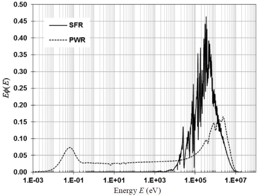
NOTE: PWR = pressurized water reactor; SFR = sodium-cooled fast reactor.
SOURCE: Lee (2020).
Neutron reaction cross sections representing neutron/nucleus reaction probabilities—in particular, fission cross section and radiative capture cross section—depend heavily on the energy of neutrons and hence the neutron flux spectrum, as well as on the type of nuclides with which the neutrons interact. Table E.1 compares key spectrum-average neutron cross sections in units of barn [b] for typical thermal and fast-spectrum reactors. Note that the fission cross section is generally much larger in the thermal spectrum, while the ratio 239Pu fission cross section to 238U capture cross section is 8.1 in the fast spectrum compared with 34–98 for the thermal spectrum. This indicates that a fast-spectrum reactor requires a large fissile enrichment of either 239Pu or 235U to attain a critical system. This feature, at the same time, also allows enhanced neutron captures in fertile nuclides (e.g., converting fertile 238U to fissile 239Pu), serving as the basis for a fast-spectrum breeder reactor.
TABLE E.1 Spectrum-Average Cross Sections for Thermal and Fast-Spectrum Reactors
| Reaction | Thermal Spectrum | Fast Spectrum | |
|---|---|---|---|
| PWR | VHTR | SFR | |
| 238U capture σγ238 (b) | 0.9 | 4.8 | 0.20 |
| 239Pu fission σf239 (b) | 89.2 | 165.0 | 1.65 |
| σf239/σγ238 | 97.7 | 34.3 | 8.14 |
NOTE: PWR = pressurized water reactor; SFR = sodium-cooled fast reactor; VHTR = very-high-temperature reactor.
SOURCE: Yang (2012).
GROUPING ADVANCED REACTORS FOR FUEL CYCLE CHARACTERISTICS
Representative reactor concepts are analyzed with a focus on material flow sheets in an effort to present and compare fuel cycle characteristics of various advanced reactor designs under development. The material flow sheets are constructed primarily with the data presented in the 2014 Nuclear Fuel Cycle Evaluation and Screening (NFCE&S) report (Wigeland et al., 2014). The flow sheets reflect three once-through cycles contrasted with a design requiring continuous fuel processing and a two-tier system combining thermal and fast-spectrum reactors. The analysis covers primarily three major concepts that have been supported by the U.S. Department of Energy following the Generation IV Roadmap release.
Fuel cycle characteristics are represented primarily in terms of the fuel composition and coolant that play a dominant role in determining the neutron flux spectrum in the reactor core. The flux spectrum, together with the fuel composition, in turn characterizes the depletion and isotopic evolution of nuclear fuel materials. This observation suggests classifying advanced reactor designs as (a) fast-spectrum reactor, (b) gas-cooled reactor, and (c) molten salt reactor, together with (d) modular LWR, as summarized in Table E.2.
TABLE E.2 Key Attributes of Advanced Nuclear Reactors Under Development
| Project Description | Power | Features | Fuel Cycle |
|---|---|---|---|
| Base Case: Large Light Water Reactor | |||
| AP1000 Reactor | 3.4 GWt | Pressurized water coolant | LEU once-through |
| Westinghouse Electric | 1.09 GWe | 15.5 MPa | 49 MWd/kgHM |
| Modular Light Water Reactor | |||
| NuScale Small | 250 MWt | Natural circulation cooling | LEU once-through |
| Modular Reactor | 77 MWe | 12 PWR modules | 41-60 MWd/kgHM |
| Fast-Spectrum Reactor | |||
| Versatile Test Reactor | 300 MWt | Na cooled | U-20Pu-10Zr metallic fuel |
| U.S. Dept. of Energy | 0.0 MWe | Na-bonded fuel | 5.0 wt% 235U |
| Natrium | 840 MWt | Na cooled | U-10Zr HALEU 16.7 wt% |
| TerraPower | 339 MWe | 1.0-m fuel column | 150 MWd/kgHM |
| ARC-100 | 286 MWt | Na cooled, superheated | HALEU metallic alloy |
| Advanced Rx Concepts | 100 MWe | steam for balance of plant | 77 MWd/kgHM |
| SEALER-55 | 140 MWt | Lead cooled, Hf and | UN HALEU 12.0 wt% |
| LeadCold | 55 MWe | Enriched 15N in fuel | 60 MWd/kgHM |
| MCFR TerraPower | 0.5–1.2 GWe | Molten chloride fuel online refueling | U-Pu HALEU 12.0 wt% 180-360 MWd/kgHM |
| eVinci Microreactor Westinghouse | 4.5 MWe | Heat pipe fuel pin design | TRISO UCO HALEU 19.8 wt%, 45 MWd/kgHM |
| Aurora Powerhouse | 4.0 MWt | Heat pipe | U-10Zr, HALEU 12-19.8 wt%, |
| Oklo | 1.5 MWe | metallic annular fuel | 20 MWd/kgHM |
| Lead Fast Reactor | 950 MWt | Lead cooled, secondary | UO2 HALEU, 13.8 wt% |
| Westinghouse | 450 MWe | supercritical water | 80 MWd/kgHM peak |
| Gas-Cooled Reactor | |||
| Xe-100 | 200 MWt | He cooled | TRISO UCO HALEU 15.5 wt% |
| X-Energy | 80 MWe | pebble-bed reactor | 160 MWd/kgHMa |
| Project Description | Power | Features | Fuel Cycle |
|---|---|---|---|
| KP-X FHR | 320 MWt | LiF-BeF2 molten salt | TRISO HALEU 19.5 wt% |
| Kairos Power | 140 MWe | pebble-bed reactor | 40-mm pebbles, 194 MWd/kgHM |
| SC-HTGR | 625 MWt | He cooled | TRISO UC HALEU 14.5 wt% |
| Framatome | 272 MWe | prismatic HTGR | 160 MWd/kgHM |
| BANR HTGR BWXT Technologies |
50 MWt 17 MWe |
He cooled prismatic HTGR | TRISO UCO HALEU 19.8 wt% |
| Energy Multiplier EM2 General Atomics |
500 MWt 250 MWe |
Pressurized He coolant | UC pellet, SiC cladding 143 MWd/kgHM |
| Molten Salt Fueled Reactorb | |||
| IMSR-400 | 400 MWt | C-moderated | UF4 LEU 4.95 wt% |
| Terrestrial Energy | 195 MWe | molten salt fuel | 29 MWd/kgHM |
| ThorCon | 557 MWt 250 MWe |
Fluoride molten salt 5% fuel salt, 95% C | 85% ThF4, 15% UF4 19.7 wt% fissile, 509 MWd/kgHM |
| LFTR Flibe Energy | 600 MWt 250 MWe |
LiF-BeF2 molten salt | LiF-BeF2 -233U F4, 19.6 wt% 194 MWd/kgHM |
| Moltex SSR-W Moltex Energy | 750 MWt | KCl coolant in cylindrical fuel pins | CANDU spent fuel as feed 150 MWd/kgHM |
a In August 2022, X-energy provided an updated burnup to the committee of 165 MWd/kg HM.
b Following a prepublication version of this report, the row heading was renamed to specify that the reactors in this category are both cooled and fueled by molten salt.
NOTE: CANDU = Canadian Deuterium Uranium; FHR = fluoride-cooled high-temperature reactor; GWt = gigawatt thermal; GWe = gigawatt electric; HALEU = high assay low-enriched uranium; HTGR = high-temperature gas-cooled reactor; LEU = low-enriched uranium; LFTR = liquid fluoride thorium reactor; MPa = megapascal; MWd/kgHM = megawatt-day per kilogram of heavy metal; MWe = megawatt electric; MWt = megawatt thermal; PWR = pressurized water reactor; TRISO = TRistructural ISOtropic.
MATERIAL FLOW SHEETS FOR REPRESENTATIVE FUEL CYCLES
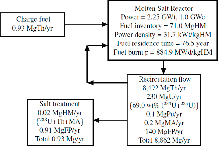
The corresponding fuel cycle characteristics are also discussed in terms of the inventories of nuclear fuel material, referred to as “heavy metal” (HM), which comprises transuranic elements, Pu, Am, Np, and Cm, and all other actinides, usually starting with Th and U, used as fuel in nuclear reactors and those produced during the fuel cycle. Among the TRUs, Am, Np, and Cm are designated as minor actinides (MAs). Representative HM flow sheets are presented in Figures E.2–E.5 for three representative reactor types for once-through fuel cycles beginning with fresh fuel, together with a continuous recycling fluid system. Figure E.6 discusses a fuel recycling configuration for a combined PWR-SFR (sodium-cooled fast reactor) configuration. All of the flow sheets are normalized to the power output of 1.0 GWe.
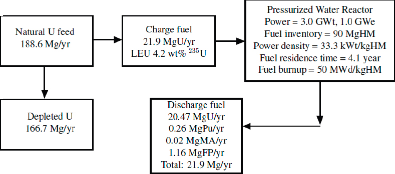
Pressurized Water Reactor
The PWR design represents the current generation of LWRs utilizing low-enrichment uranium fuel with 235U enrichment less than 5.0 wt%. The AP1000 plant, representing Generation III+ designs, features fuel assemblies with an effective length of 4.27 m (14 feet) and rated power generation of 1.1 GWe, with a heat-to-electricity conversion efficiency of 33 percent. The NuScale Small Modular Reactor design under development features 12 smaller PWR units with a fuel length reduced to 2.0 m and a rated power of 77 MWe each. The average energy of neutrons in a PWR core is approximately 0.25 eV.
A typical PWR core is loaded with 200 UO2 fuel assemblies with a total inventory of 90 MgU or 90 MgHM at the beginning of cycle, as indicated in Figure E.2. One-third of the fuel elements with an inventory of 30 MgHM
are discharged and new fuel elements are loaded and shuffled with partially used fuel elements with a cycle length of 18 months. This explains the charge and discharge fuel inventory of 21.9 MgHM per year and the nominal fuel residence time of 4.5 years, reduced to an effective fuel residence time of 4.1 years accounting for routine maintenance. This then yields a discharge fuel burnup of 50 MWd/kgHM or 50 GWd/MTU for fuel elements operating at a power density of 3.0 GWt//90 MgHM = 33.3 kWt/kgHM. The discharged fuel elements contain 4–5 percent of FPs, 1.2 percent TRU, including 0.1 percent MA, and 94–95 percent unused uranium.
An estimate of the FP generation rate may be obtained from an approximate relationship (Lee, 2020):
Fuel burnup [MWd/kgHM] = 939 fima (fissions per initial metal atom),
with the observation that approximately 200 MeV of energy is released per fission event.
With a discharge burnup of 50 MWd/kgHM for the PWR configuration, the energy balance statement yields fima = 0.053 or an FP yield of 1.2 Mg/year, in agreement with the detailed NFCE&S calculation included in Figure E.2.
Approximately two-thirds of the 93 LWRs operating in the United States in 2022 are PWRs, and the rest of the fleet are BWRs. The fuel elements or bundles are a bit smaller in a typical BWR core, which contains a slightly larger number of fuel bundles. Thus, it is reasonable to assume that the fuel cycle characteristics of Figure E.2 are applicable also to BWR plants. Several modular LWR plants under development, including the NuScale Small Modular Reactor, feature low-enrichment uranium oxide fuel similar to that used in LWR plants and fuel cycle characteristics will not change much from those of Figure E.2, subject to possible improvements with increased thermal efficiency.
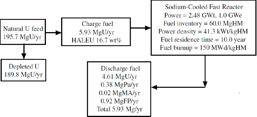
Sodium-Cooled Fast Reactor
The SFR design features one of the key Generation IV reactors fueled with uranium and TRU elements in the form of metallic U-Zr or U-Pu-Zr fuel rods. The SFR core typically features tight fuel assembly designs with the assembly length much shorter than that for LWR designs. Liquid-sodium coolant produces a hard neutron spectrum with an average neutron energy around 0.1–0.2 MeV, providing flexibility for using a variety of fuel materials including TRUs from used LWR fuel assemblies. In the fast neutron spectrum, the fission-to-capture cross section ratio for 235U or 239Pu is smaller than that in the thermal spectrum of the LWRs by an order of magnitude, which requires higher fissile enrichments for fast reactors, represented by the high-assay low-enriched uranium (HALEU) fuel composition planned for the demonstration core of the TerraPower Natrium reactor. This feature is discussed in connection with Table E.1.
SOURCE: Adapted from NFCE&S Evaluation Group 1, Wigeland et al. (2014).
The higher average energy of the fast-spectrum reactors would allow efficient production of fissile Pu from 238U and could work efficiently with the MAs Am, Np, and Cm, allowing for the breeding of fissile materials for subsequent fast reactor cycles or as feed material for LWRs. With the HALEU fuel with 16.7 wt% fissile 235U enrichment, the charge fuel inventory per year and HM inventory in the Natrium Advanced Type 1B Metal core, summarized in Figure E.3, are both reduced significantly from the PWR counterparts in Figure E.2. TerraPower plans to complete the development of fuel element designs without sodium bonding for the Type 1B Metal Core. With an increased thermal efficiency, the Natrium core design, as a fast-spectrum reactor, indicates a three-fold increase in the discharge fuel burnup and a four-fold reduction in the used nuclear fuel inventory discharged, compared with an equivalent 1.0-GWe LWR plant. It should, however, be noted that the depleted U inventory increases by ~15 percent from the LWR counterparts.
High-Temperature Gas-Cooled Reactor
The design utilizes submillimeter diameter TRistructural ISOtropic (TRISO) particles with multiple pyrolytic graphite coatings that form the basic building block. The prismatic design loads TRISO particles, often featuring uranium oxycarbide (UCO) fuel, into graphite pin cells or compacts, while in the pebble-bed design the TRISO particles are packed into graphite spheres with a diameter of 40–60 mm. The high-temperature gas-cooled reactor (HTGR) designs provide mostly thermal spectrum but may be configured to provide an epithermal spectrum with an average neutron energy in the eV range.
The fuel characteristics summarized in Figure E.4 illustrate a HALEU design with a fissile U enrichment of 15.5 wt% in a thermal neutron spectrum of a graphite-moderated HTGR, similar to the Xe-100 pebble-bed reactor design. Utilizing a HALEU design allows a charge and discharge fuel rates similar to those for the HALEU-fueled SFR of Figure E.3. With a high He coolant temperature possible with the HTGR, a higher thermal efficiency of 50 percent could be attained, compared with 41 percent for the Natrium design. With a higher power density of 67.1 kWt/kgHM, compared with 41.3 kWt/kgHM for the Type 1B Natrium core, a discharge burnup of 120 MWd/kgHM could be obtained for the HTGR in 4.9 years compared with a discharge burnup of 150 MWd/kgHM in 10 years for the Natrium design. The FP production rate is reduced somewhat also for the HTGR design with a higher thermal efficiency compared with the SFR design.
SOURCE: Adapted from TerraPower communication, dated January 14, 2022. Copyright © 2022 TerraPower, LLC. All rights reserved.
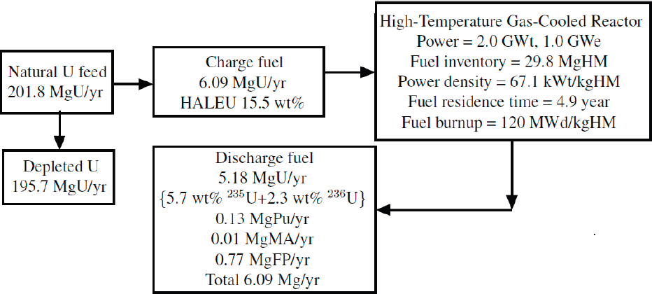
SOURCE: Adapted from NFCE&S Evaluation Group 2, Wigeland et al. (2014).
Molten Salt Reactor
The molten salt reactor (MSR) design illustrates the use of various salts, including LiF-BeF2 molten fluoride salt, as a coolant for the core, as well as the salt admixed with fuel. The material flow sheet in Figure E.5 represents a molten fuel design that allows continuous circulation of the fuel salt with an equivalent period of 3 days, or 121.67 times per year, indicating a large flow rate of fuel salt summed over a year as high as 8,862 Mg/year. The fuel residence time of 76.5 years is estimated from the limited recycle MSR case, represented as Evaluation Group 10, and essentially indicates that the fuel salt circulates through the system indefinitely, resulting in a large fuel burnup.
The MSR system provides a continuous online fuel salt treatment with low processing loss so that the material processed and discharged consists primarily of FPs produced during the reactor operation. The circulating salt comprises Th as the feed material producing 233U as the fissile material demonstrating the significant potential of a Th converter operating with merely 0.93 Mg/year of Th as feed material; this may be compared with 21.9 Mg/year of low-enrichment uranium (LEU) fuel for the once-through PWR cycle in Figure E.2. In the thermal-spectrum MSR design featuring a Th-U fuel cycle in Figure E.5, the production of TRU elements is very small, so that the sum of the 233U, Th, and MA inventories discharged through the fuel salt treatment is merely 0.02 Mg/year. The fissile U content, comprising 233U and 235U, is 69.0 wt% in the recirculating fuel stream, and may require denaturing the fuel cycle with the addition of 238U.
Depending on the salt utilized, an MSR could be configured either as a thermal or fast-spectrum reactor. With KCl salt as the coolant and UPuCl3 as the fuel, the Moltex design indeed suggests a fast-spectrum reactor configuration with an online refueling strategy and spent Canadian Deuterium Uranium (CANDU) fuel used as the feed material.
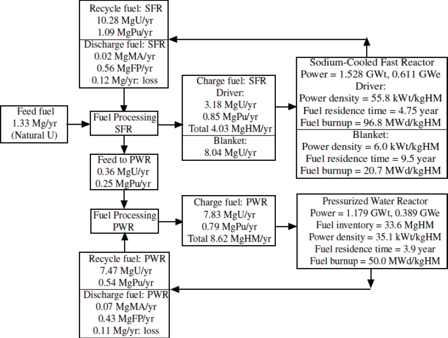
Two-Tier Coupled SFR-PWR System
Coupling an SFR with a full breeding capability to a PWR in a symbiotic manner, the system could recycle the Pu generated in both the PWR and SFR cores. The flow sheet of Figure E.6 represents a synergistic arrangement where only Pu, together with the uranium fuel, is recycled and MAs and FPs are sent to a repository. The only feed material required then is a small amount of natural uranium for the combined system replenishing the FPs and MAs to be sent to a repository.
The coupled system is structured so that the combined power output is 1.0 GWe, with a 60%–40% split between
SOURCE: Adapted from NFCE&S Evaluation Group 26, Wigeland et al. (2014).
the SFR and the PWR. For the SFR itself, the power production is split 90%–10% between the driver and blanket regions. The PWR configuration is nearly equivalent to that of Figure E.2, if the power output is normalized to 1.0 GWe, with the fuel residence time of 3.9 year compared with 4.1 year in Figure E.2 and the identical discharge fuel burnup of 50 MWd/kgHM. The main difference, of course, is the PWR use of Pu remaining from the previous PWR cycle combined with Pu produced in the SFR. With full recycling, the inventory of U and Pu from the previous SFR cycle is split between the charge to the SFR and additional mix to the PWR to bring up the required fissile contents for the PWR charge fuel. It should be also noted that the discharged fuel from both the SFR and PWR comprise MA and FP, and a total of 0.23 Mg of inventory, out of a total feed inventory of 1.33 Mg of natural U (i.e., equivalent to 17 percent of the total feed stream, is assumed lost during the recycling). Furthermore, it is useful to note that the 60%–40% power split between the SFR and PWR is approximately represented in the FP production split of 0.56 Mg versus 0.43 Mg. The total discharge fuel inventory, including the reprocessing loss, is naturally equal to the total feed rate of 1.33 Mg/year, which compares with the discharge rates of 21.9 Mg/year for the open-cycle PWR in Figure E.2 and 5.9 Mg/year for the open-cycle SFR in Figure E.3.
Two important final observations relate to (a) net Pu production of (1.09–0.85 = 0.24) Mg in the SFR versus net Pu consumption of (0.79–0.54 = 0.25) Mg in the PWR and (b) MA production of 0.02 Mg in the SFR versus 0.07 Mg in the PWR, despite the 60%–40% power split between the two reactors. These observations translate to a key potential of the SFR serving as a breeder of fissile Pu with a minor negative impact due to tracer quantities of MA present in the recycled fuel. These features are not explicitly illustrated in the Natrium design summarized in Figure E.3, because the design features U-Zr HALEU fuel.
COMPARISON OF MATERIAL FLOW AND REPOSITORY METRICS
The charge and discharge fuel material flows illustrated in Figures E.2–E.6 are summarized in Table E.3 and compared to clarify the characteristics of the five fuel cycles chosen to represent advanced reactor designs evaluated. The repository metrics including radioactivity at 100 and 100,000 years are compared for the three advanced reactor designs, together with the reference PWR and two-tier SFR-PWR recycle system. In the NFCE&S report, an adjustment is made to the discharge fuel inventories and the corresponding repository metrics to normalize the thermal efficiency to 33 percent selected for the reference PWR design (Wigeland et al., 2014). For the analysis of repository
SOURCE: Adapted from NFCE&S Evaluation Group 29, Wigeland et al. (2014).
metrics, the committee decided not to adopt the normalization process, because the increased thermal efficiencies of the advanced reactor designs represent a unique feature of the advanced concepts and hence should be retained.
For LWRs with ~33% thermal efficiency, FP inventories reflect a simple rule of thumb that a 1.0-GWe nuclear power plant consumes approximately 1.0 Mg/year of fissionable material. Thus, 1.0-GWe plant produces approximately 1.0 Mg of FPs in one year, as quantified via fima. (The FP inventories are reduced for designs with higher thermal efficiency.) The yields for short- and long-lived FPs of interest in used fuel management and geologic repository analysis depend somewhat on the neutron flux spectrum and fissile nuclides, but the sum of FP yields of interest appear nearly independent of the fuel cycle.1
Table E.3 summarizes the results of spent nuclear fuel and high-level waste (HLW) inventory in terms of its mass, radioactivities at 100 years and 100,000 years after discharge. These data are normalized per energy generated in order to have fair comparisons between different types of reactors. The time 100 years is selected to represent requirements for handling/storage of spent nuclear fuel and corresponding heat generation for disposal engineering designs in the geologic repository. Geologic repository loading is often limited by decay heat. While not an exact surrogate, the radioactivity and decay heat at 100 years provide a relative indication of the challenge of disposal of such waste.
Similarly, a time of 100,000 years after discharge is selected to represent the long-term isolation challenges in a deep geologic repository. The activity of spent nuclear fuel (SNF)/HLW at 100,000 years per energy generated represents the long term hazard of the SNF/HLW. It represents the total “hazard source term” of the inventory without considering the accessibility of the hazard. Tables E.4 and E.5 present the key contributing radionuclides for each of the advanced reactor types.
___________________
1 The paragraph was modified following a prepublication version of the report to clarify that the rule of thumb applies only to light water reactors with 33 percent thermal efficiency, and that higher thermal efficiency designs will have reduced fission product inventories.
TABLE E.3 Spent Nuclear Fuel Inventory and Repository Metrics of Advanced Nuclear Reactors
| Fuel Cycle and Reactor Type (Reference) | Spent Nuclear Fuel Inventory (Mg/GWe-yr) | Radioactivity at 100 years (MCi/GWe-yr) | Radioactivity at 105 years (kCi/GWe-yr) |
|---|---|---|---|
| Light water reactor LEU PWR (NFCE&S EG01) | 21.92 | 1.34 | 1.65 |
| Fast-spectrum reactor HALEU (TerraPower Natrium) | 5.93 | 0.53 | 1.58a |
| Gas-cooled reactor HALEU TRISO (NFCE&S EG02) | 6.09 | 0.94 | 1.35 |
| Molten salt reactor HALEU Th-233U (NFCE&S EG26) | 0.93 | 0.96 | 1.02 |
| Two-tier SFR-PWR Recycle (NFCE&S EG29) | 1.33 | 1.01 | 0.82 |
a Excludes contributions from isometric.
NOTE: HALEU = high-assay low-enriched uranium; LEU = low-enriched uranium; NFCE&S = nuclear fuel cycle evaluation and screening; PWR = pressurized water reactor; SFR = sodium-cooled fast reactor; TRISO = TRistructural ISOtropic.
TABLE E.4 Spent Nuclear Fuel and High-Level Waste Activities at 100 Years (kCi/GWe-yr)
| PWR (EG01) | SFR (Natrium) | HTGR (EG02) | MSR (EG26) | SFR-PWR (EG29) | |||||
|---|---|---|---|---|---|---|---|---|---|
| Total: | 1,340 | Total: | 530 | Total: | 940 | Total: | 959 | Total: | 1,010 |
| 137Cs | 341 | 137Cs | 262 | 137Cs | 231 | 137Cs | 245 | 137Cs | 292 |
| 137Ba* | 322 | 90Sr | 168 | 137Ba* | 219 | 90Sr | 235 | 137Ba* | 277 |
| 90Y | 215 | 238Pu | 30 | 90Sr | 161 | 90Y | 235 | 241Am | 167 |
| 90Sr | 215 | 239Pu | 21 | 90Y | 161 | 137Ba* | 231 | 90Y | 99 |
| 241Am | 122 | 240Pu | 8 | 241Am | 87 | 90Sr | 99 | ||
NOTE: HTGR = high-temperature gas-cooled reactor; MSR = molten salt reactor; PWR = pressurized water reactor; SFR = sodium-cooled fast reactor; * indicates nucleus in an excited state.
TABLE E.5 Spent Nuclear Fuel and High-Level Waste Activities at 100,000 Years (Ci/GWe-yr)
| PWR (EG01) | SFR (Natrium) | HTGR (EG02) | MSR (EG26) | SFR-PWR (EG29) | |||||
|---|---|---|---|---|---|---|---|---|---|
| Total: | 1,650 | Total: | 1,580 | Total: | 1,350 | Total: | 1,020 | Total: | 818 |
| 239Pu | 494 | 239Pu | 1,180 | 239Pu | 228 | 99Tc | 245 | 99Tc | 289 |
| 99Tc | 304 | 99Tc | 254 | 99Tc | 210 | 93Zr | 62 | 239Pu | 137 |
| 242Pu | 61 | 93Zr | 48 | 234U | 77 | 93Nb* | 59 | 233Pa | 43 |
| 93Zr | 56 | 135Cs | 40 | 222Rn | 52 | 209Pb | 53 | 237Np | 43 |
| 93Nb* | 54 | 234U | 20 | 218Po | 52 | 213Bi | 53 | 135Cs | 39 |
| 234U | 53 | 237Np | 12 | 226Ra | 52 | 217At | 53 | 93Zr | 36 |
| 233Pa | 37 | 236U | 10 | 214Pb | 52 | 221Fr | 53 | 93Nb* | 35 |
| 237Np | 37 | 214Bi | 52 | 229Th | 53 | 126Sb* | 16 | ||
| 222Rn | 35 | 210Po | 52 | 225Ra | 53 | 126Sn | 16 | ||
| 214Pb | 35 | 210Pb | 52 | 225Ac | 53 | 233U | 15 | ||
| 218Po | 35 | 214Po | 52 | 213Po | 51 | 213Bi | 14 | ||
| 214Bi | 35 | 210Bi | 52 | 233U | 50 | 217At | 14 | ||
| 226Ra | 35 | 230Th | 52 | 234U | 16 | 221Fr | 14 | ||
| 210Pb | 35 | 242Pu | 43 | 126Sb* | 16 | 225Ra | 14 | ||
| 210Po | 35 | 93Zr | 38 | 126Sn | 16 | 225Ac | 14 | ||
| 210Bi | 35 | 93Nb* | 37 | 210Po | 11 | ||||
| 214Po | 35 | 233Pa | 27 | 214Po | 11 | ||||
| 230Th | 35 | 237Np | 27 | 222Rn | 11 | ||||
| 135Cs | 15 | 135Cs | 17 | ||||||
| 233U | 13 | ||||||||
NOTE: HTGR = high-temperature gas-cooled reactor; MSR = molten salt reactor; PWR = pressurized water reactor; SFR = sodium-cooled fast reactor; * indicates nucleus in an excited state.
Key general observations are offered:
- With the fission process releasing two FPs and approximately 200 MeV of energy per fission, a 1.0-GWe power plant consumes approximately 1.0 Mg/year of nuclear fuel and produces 1.0 Mg/year of FPs, making the FP inventory in UNF proportional to the thermal energy generated. The discharge fuel and FP inventories are thus reduced for designs with a higher thermal efficiency.
- Effective use of HALEU with a thermal efficiency of 40–50 percent for the SFR and HTGR, compared with 33 percent for the PWR, reduces the fuel inventory to 25 percent of the PWR inventory. The continuous circulating MSR and coupled SFR-PWR system requiring fuel reprocessing reduce the UNF inventory to 5 percent of the PWR discharge fuel.
- On a per-energy-generation basis, radioactivity at 100,000 years, with a significant portion from actinides, is reduced in SFR from a few percent below the level of PWR to somewhat more than a factor of 2 for SFR-PWR as compared to PWR.2 These reductions do not have, however, significant impacts on the safety of a repository if geochemical and geologic conditions of the repository site are carefully chosen to limit the mobility and accessibility of the actinides.
___________________
2 This sentence was modified following a prepublication version of the report to clarify the comparison between radioactivity at 100,000 years for these reactor designs.
- Together with a priority given for the development of a geologic repository for the legacy UNF, additional effort effectively utilizing fuel reprocessing could help reduce the future accumulation of UNF from advanced reactors under development.
- The coupled SFR-PWR system features a net production of Pu in the SFR, which is consumed in the PWR. The production of MAs is significantly smaller in the SFR than in the PWR. These observations translate to a key potential of the SFR serving as a breeder of fissile Pu with a minor negative impact due to tracer quantities of MAs in the recycled fuel.


