
4
Corrosion of Buried Steel
As described in Chapter 2, metallic corrosion involves oxidation (anodic) and reduction (cathodic) half-cell reactions, where the metal oxidation reaction is the anodic reaction, and the reduction of a species in the subsurface (e.g., oxygen, water, or H+ ions) is the cathodic reaction. Although the electrochemical fundamentals of metallic corrosion in the subsurface are always the same, the corroded component might look different under different conditions because there are several forms of corrosion. Corroded steel might exhibit uniform attack over its entire surface, or the corrosion might be localized at a few spots on the steel. Alternatively, the steel might exhibit little change on the surface, but the absorption of hydrogen might make the steel brittle. This chapter provides details regarding the fundamentals of buried steel corrosion, and different forms of corrosion are addressed.
GENERAL CORROSION
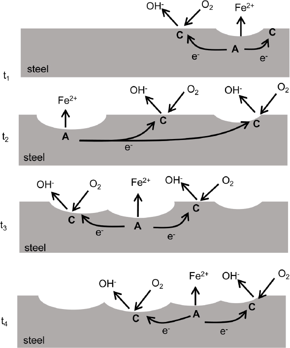
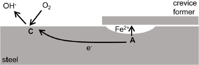
Figure 4.1 illustrates the reactions occurring at anodic and cathodic sites on a buried steel component. Iron dissolution occurs at anodic sites, and reduction reactions occur at closely located cathodic sites. Electrons flow between them. The anodic and cathodic sites on the steel surface often will move continually across the steel surface such that all parts of the surface eventually experience the anodic dissolution reaction and dissolve (i.e., corrode). The resulting uniform wastage of material across the surface is known as general or uniform corrosion. The corrosion rates of general corrosion can be estimated by the rate of loss of steel thickness or by the rate of weight loss normalized by the exposed area. Buried steel commonly corrodes by a general corrosion mechanism, although the attack might be localized in certain spots known as pits (Romanoff, 1964). General corrosion will often be present along the surface of buried steel components unless the surface is coated with a dielectric, or an electrically insulating, material. The severity of general corrosion depends on the soil conditions (e.g., moisture, degree of aeration, pH). The corrosion can be so minimal as to be insignificant, or it can be severe with a significant impact on the durability and service life of the steel. Typical general corrosion rates in soil result in a loss of about 0.045 millimeters (mm), with the deepest pits of about 0.23 mm over a period of 9 years (Shreir et al., 1994).
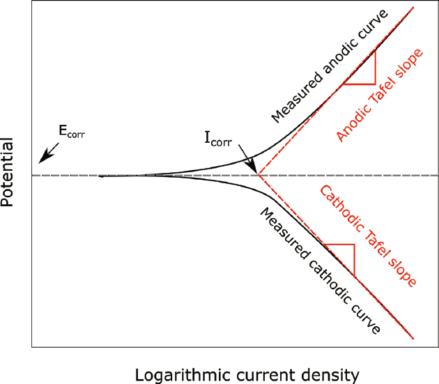
As described in Chapter 3, the oxidizing power of the underground environment, which is controlled by the degree of aeration and the presence of other oxidizing species, will impact the corrosion potential. The oxidizing power can have a large effect on the rate of general corrosion because the corrosion rate increases exponentially with an increase in electrochemical potential. The equation describing this relationship is called the Tafel equation. The Tafel slope is the slope of the semilogarithmic plot of potential versus log of the current density (a measure of
rate) (see Figure 4.2). The fundamental understanding of corrosion kinetics as expressed by the Tafel equation can be used in an accurate determination of corrosion rate (corrosion current density) using different electrochemical methods. The kinetics of the cathodic reaction often also exhibit exponential dependence of current density on potential (i.e., the Tafel equation but with a different Tafel slope). The curve representing the cathodic oxygen reduction reaction (see Equation 2.2) is often a vertical line, which indicates that the rate of the reaction is limited by the transport of oxygen to the steel surface by diffusion. In this case, the rate of steel corrosion can be controlled totally by the rate of transport of the cathodic reactant (i.e., dissolved oxygen) to the metal surface. In liquids, transport is accelerated by convection, even natural convection that occurs in the absence of any forced flow; however, convection is limited in soils with sand-size and smaller particles due to reduced flow rates as water flows through the small tortuous paths in pore spaces between. As a result, transport of oxygen to the surface of buried steel might be diffusion limited and occur at a low rate.
The temperature of the environment can affect the corrosion rate in multiple ways. The electrochemical reactions represented by Equations 2.1–2.5 are thermally activated, meaning that their rate will increase, often exponentially, with increasing temperature. Therefore, corrosion rate tends to increase with increasing temperature. Furthermore, diffusion is also a thermally activated process, and so for the case of corrosion limited by oxygen diffusion, the corrosion rate will also increase with increasing temperature. However, the solubility of oxygen in water decreases with increasing temperature, and this will tend to decrease the rate of corrosion. For steel corroding in liquids, these factors balance to result in a maximum corrosion rate at 70°C.
LOCALIZED CORROSION MECHANISMS FOR BURIED STEEL
As shown in Figure 4.1, anodic and cathodic sites can continually move across the surface with time, causing general corrosion or uniform steel loss. However, when the anodic and cathodic sites are spatially fixed (see Figures 4.3–4.7), the corrosion will be localized at the fixed anodic sites. Such localized forms of corrosion are described in the next sections, and it is important to distinguish between general and localized corrosion because of the structural implications related to targeted attack. The same fundamental electrochemical mechanisms control the corrosion, but each form of corrosion has a different appearance. One distinguishing difference is the spatial separation of the anodic and cathodic sites. For general corrosion, in which the anodic and cathodic sites continuously move, their separation distance might be on the order of nanometers. The separation for localized corrosion can be micrometers (pitting corrosion), millimeters (crevice corrosion), or centimeters to meters (macrocell corrosion).1 In buried-steel applications, general corrosion, pitting, and macrocell corrosion are generally the corrosion mechanisms that need to be mitigated or accounted for during design or analysis of performance. Other forms of corrosion including galvanic corrosion and crevice corrosion can be avoided with proper design. Mechanisms for localized corrosion methods are described in the next sections.
___________________
1 Terminology and scales associated with localized corrosion had to be defined by the committee through research and deliberation. For example, it took some time for committee members to realize that the corrosion engineers and metallurgists on the committee defined the pitting corrosion and its scales differently than the geotechnical and civil engineers on the committee.
Pitting Corrosion
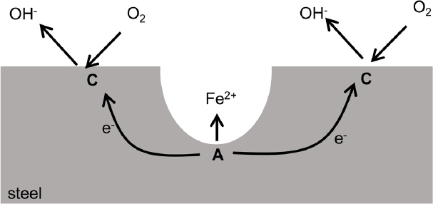
Pitting is localized corrosion that results when the anodic site is spatially fixed on a boldly exposed surface (see Figure 4.3) as opposed to within an occluded crevice. The separation distance between anodic and cathodic sites is on the order of micrometers to millimeters. The anodic reaction inside the pits is supported by cathodic reaction on the nearby surface. Pits usually initiate at susceptible sites on the surface associated with metallurgical features. Once a pit initiates, it tends to propagate because oxygen is depleted inside the pit while being readily available on the outer surface. This allows continued cathodic oxygen reduction reactions only on the exposed surface. A single deep pit in pipelines can initiate a leak that is large enough to require immediate repair and response. On the other hand, for structural systems where containment is not one of the functions, a deep pit may not affect performance and service life.
Aboveground pitting is commonly associated with a surface that is protected by a thin oxide film called a passive film. Plain carbon steels commonly used in underground environments may form a protective iron oxide layer if the local pH is relatively high. As the oxide layer begins to break down, for example, through reactions with dissolved ions such as chlorides, the steel becomes susceptible to pitting corrosion. Cations generated by the pitting process react with water causing strong acidification within a pit, and aggressive anions such as chloride are enriched in a pit by a process called migration. As a result, the environment in a pit often resembles hydrochloric acid, creating an aggressive environment that promotes sustained dissolution in the pit. However, most underground environments have pHs in which these passive films do not generally form on plain carbon. The pits commonly observed in buried steel can be better classified as a form of microcell corrosion as described below. Pits in buried steel can also result from microbially influenced corrosion (MIC), as also described below.
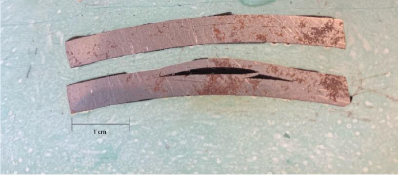
Multiple converging pits, hemispherical pits with interior pitting, multiple tiers within pits, striations within pits, and tunneling morphologies have all been identified in case studies of MIC involving carbon steel (Chen et al., 2021; Islam et al., 2016; Pope, 1990). As mentioned above, local pit environments are often acidified by reactions of dissolved cations with water. Pits formed by MIC are similarly acidified but are also influenced by microbial metabolic processes. In their review of sulfate-reducing bacteria (SRB) corrosion, Enning and Garrelfs (2014) included images of localized corrosion on the exterior of a buried carbon steel pipe exhumed from a waterlogged, anoxic, sulfate-rich (1.4 mm) soil (see Figure 4.4). The images are consistent with previous descriptions of MIC of carbon steel.
Crevice Corrosion
Crevice corrosion (see Figure 4.5) occurs in occluded regions formed by the close contact of a metal and a nonmetal (polymer or ceramic) or another piece of the same metal with cathodic-anodic spatial separation on
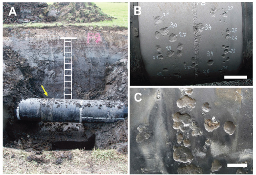
SOURCE: Enning and Garrelfs (2014).
the order of millimeters. One example of this is the connection of a structural element (e.g., nuts, bolts, washers, bolt holes). Local contact with rock might also be the site of crevice corrosion. The occlusion causes a physical separation of anodic and cathodic sites because of the limited supply of oxygen (the common cathodic reactant) in the crevice. This spatial separation leads to the same development of a corrosive local environment as occurs in a pit. In fact, a deep pit is a crevice. The difference between pitting and crevice corrosion is that crevice corrosion will initiate more easily than pits. If the entire surface of a buried steel structure is not completely covered with a protective coating, crevice corrosion can initiate where there is a small gap between the coating and the metal. Crevice corrosion can be avoided by sealing crevices, applying cathodic protection (CP), or using more corrosion-resistant materials.
Galvanic Corrosion
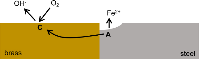
Galvanic corrosion (see Figure 4.6) occurs when dissimilar metals are in electrical contact in the same electrochemical environment. The metal that has the more negative electrode corrosion potential (i.e., it is less noble) becomes the dominant anodic site and corrodes more quickly than when not electrically connected. The metal with less negative corrosion potential (i.e., more noble) becomes the dominant cathodic site and corrodes more slowly than when not electrically connected. The relative nobility of metals is indicated by the galvanic series, which lists the corrosion potential of metals from relatively active metals such as zinc to relatively noble metals
such as copper. Figure 4.6 shows an example of the galvanic coupling of steel with brass, which would result in accelerated corrosion of the steel near the contact point with the brass.
Galvanic corrosion may occur when bolt materials differ from the material used in the infrastructure component (e.g., plain steel bolts on sections of stainless steel or weld materials that differ in composition from the base steel). Galvanic corrosion can also occur when galvanized (i.e., coated with zinc) and plain steel are in contact (e.g., when a nongalvanized temporary structure comes in contact with permanent galvanized reinforcements or when a nongalvanized reinforcing steel and galvanized tie strips come in contact in a concrete facing wall). Galvanic corrosion is not usually considered a localized form of corrosion but is included in this section because the lateral extent of the galvanic interaction is often limited to the region close to the dissimilar metals’ connection, as is shown in Figure 4.6.
There are examples wherein galvanic corrosion is used to the engineer’s advantage and contributes to corrosion management practices. For example, coating steel with zinc creates a galvanic couple between the zinc and steel surface. The zinc will corrode preferentially to the steel and the underlying steel will not be consumed until the zinc coating is exhausted, thus affording corrosion protection to the steel.
Macrocell Corrosion
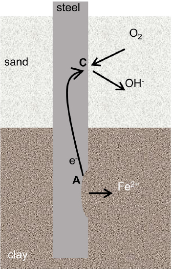
In a variety of steel structures including piles, soil nails, or pipelines (see Table 2.1 for descriptions), localized regions of the steel may be exposed to greater levels of oxygen than other regions. Those aerobic (oxygen-rich) regions would be the preferential cathodic sites, and the oxygen-poor regions would be preferential anodic sites. In some cases, such as retaining-wall systems that use ground anchors to support a steel facing, current may travel through millimeters to meters of steel from the anodic site (e.g., the bonded zone of the anchor) to the cathodic sites (e.g., the steel face). An area of steel serving as a net anode in this reaction will corrode at a higher rate than an area serving as a net cathode. Figure 4.7 represents a pile that is driven through different soil types, specifically a loose sand layer over a dense clay. The less-dense soil (i.e., the loose sand) allows greater access to oxygen and is the site of the cathodic reaction, with corrosion focused in the region with less oxygen.
Macrocell corrosion driven by differences in oxygen concentration can also be referred to as “concentration cell corrosion” or “differential aeration corrosion.” This type of corrosion might result in localized attack of the steel to form a region often referred to as a pit. However, this pitting of buried steel is different than the pits formed on passive steel that might occur in high-pH soils containing chloride ions, as described above. The latter situation, which is rare, would exhibit small spots of rapid attack on a surface that is otherwise relatively unattacked. The more common pitting of buried steel, resulting from microcell corrosion, takes the form of heavy corrosion across the component, with some sites exhibiting more rapid thinning. The rate of this type of pitting is often greater in poorly aerated soils (Romanoff, 1957).
Macrocell corrosion can occur, for example, in drilled shafts where concrete covers the reinforcing steel (see Table 2.1) or when the cover is breached from voids or a soil inclusion at the edges of the concrete. A macrocell is created between the portion of the bar that is embedded within concrete and the portion exposed with the void space. Galvanic currents driven by dissimilar media like this can cause the corrosion rate of exposed steel to increase by 3.3 to 5.6 times (Sarhan et al., 2002).
Stray-Current Corrosion
Stray-current corrosion occurs when buried steel inadvertently interacts with nearby sources of alternating current or direct current (DC) voltage. One common producer of stray currents is DC-powered transit or other rail systems (Sankey and Hutchinson, 2011). Stray electrical currents may also exist around electrical transmission systems, waterfront structures in saltwater, CP systems, or welding shops. They often encounter buried metallic structures including buried utility pipes and cables, underground storage vessels, and reinforced concrete structures. This type of corrosion is most commonly observed on structures that have large dimensions in one direction such as pipelines, and, in fact, much of the experience with stray-current corrosion is from the observed performance of pipelines. Sheet piling and other piling that are electrically continuous also can experience stray-current corrosion (Beavers and Durr, 1998). In particular, buried metallic structures in high-density urban areas are at risk.
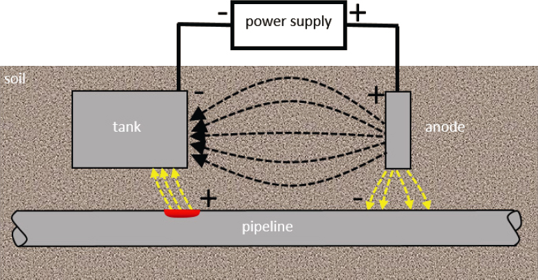
CP is a means of protecting buried steel by making it the cathode of an electrochemical cell and is described in more detail in Chapter 5. Figure 4.8 shows a schematic for stray-current corrosion associated with CP, where a DC power supply passes cathodic current to a steel tank from a remote anode to reduce the corrosion rate of the tank. In this diagram, a pipeline is unknowingly situated near the tank. Electrical current will always take the path of least resistance, which is often a straight line. However, because the electrical resistivity of the steel pipe is much less than the soil, the lowest resistance follows a path through the pipe. The current enters the pipe at a location near the CP anode, resulting in a localized cathode where oxygen is reduced (cathodic reaction), passes through the pipe as electrical current, and then exits the pipe at a location near the tank, resulting in a localized anode where metallic iron of the steel pipe is oxidized (anodic reaction).
ENVIRONMENTALLY INDUCED CRACKING
Environmentally induced cracking (EIC) involves the synergistic interactions of stress and a corrosive environment (Fletcher, 2005). There are generally three types of EIC: hydrogen embrittlement, stress corrosion cracking (SCC), and corrosion fatigue. Note that the terminology can be confusing because some experts consider hydrogen embrittlement to be a mechanism of SCC.
Hydrogen can be generated through the cathodic hydrogen evolution reaction that accompanies corrosion in most anoxic (i.e., without oxygen) environments (Equations 2.4 and 2.5). Hydrogen atoms are very small and may be absorbed into the corroding steel in relatively high concentrations, and given the volume of material involved, can cause hydrogen blistering (see Figure 4.9). Additionally, high-strength steel can become brittle due to absorbed hydrogen, leading to possible catastrophic failure under load. This phenomenon is referred to as hydrogen embrittlement.
SCC involves the synergistic interactions of stress and a corrosive environment. In fact, three factors must be present for SCC: tensile stress, a susceptible material, and a particular environment that promotes SCC of the material. SCC is prevented by the elimination of one of those three factors. SCC of pipelines can occur from the inside because of corrosive products being transported, but this is not within the scope of this report. Exterior SCC of pipelines has been observed under disbonded coatings. For example, coal tar coatings are often susceptible when the local pH and potential have been altered by CP (coatings and CP are described in Chapters 4 and 5) (Beavers, 2014). Higher temperature increases susceptibility, and a sufficiently high pH or low potential can prevent SCC. Stresses in pipelines can arise from internal pressurization, residual stresses at welds, or bending from movement
SOURCE: Photo by Elizabeth Rutherford, committee member.
of the supporting soil. A different type of SCC in pipelines has been observed under coatings that are impermeable to CP (e.g., polyethylene tape) if water from the environment can reach the pipe surface. The nature of the cracking in this case is different in that it is transgranular instead of intergranular.
Steel components in civil structures such as rock bolts are not susceptible to the same forms of cracking as pipelines because CP is not used. However, cracking from hydrogen embrittlement is possible for high-strength steel structures (Grade 150 or higher) when the element is subject to tensile stress (e.g., prestress) exceeding 50 percent of its ultimate tensile strength and the element is in direct contact with the subsurface environment (i.e., subject to chlorides or free hydrogen) (Fédération Internationale de la Précontrainte, 1986; Withiam et al., 2002). SCC is mitigated by incorporating corrosion protection in the design of those metal tensioned elements such that the steel tendons are isolated from the underground environment. For example, isolation may be achieved with a system that includes coating the steel with grease, and covering it with a plastic sheath that is then surrounded by grout (Post-Tensioning Institute, 2014). In this case, service life is dependent on the workmanship of the installation and the durability of the materials used in the corrosion protection system.
Time-varying stresses can cause cracking of metals by a phenomenon called metal fatigue even when the stresses are relatively low. The cracking is faster in a corrosive environment, which is a form of corrosion called corrosion fatigue. The loads on buried structures are usually invariant, although varying internal pipe pressure can cause a variable hoop stress that can accelerate the crack growth rate (Beavers, 2014).
MICROBIALLY INFLUENCED CORROSION
MIC of buried steel is the result of microbial activities, typically within biofilms that are bound to the surface of buried steel (see Chapter 3 for a description of microorganisms in the subsurface). The term MIC does not denote a specific mechanism for corrosion but rather refers to the microbial activities that can create a more corrosive environment. Microbial activities that can influence the corrosion of steel include (1) conversion of a protective iron oxide to a less protective sulfide by sulfide-producing procaryotes (SPPs), (2) direct removal of a protective oxide layer by iron-reducing bacteria (IRB), (3) direct removal of a protective oxide layer by acid-producing bacteria (APB), and (4) direct uptake of electrons from iron. Specific consequences are determined by reactions within biofilms.
Microorganisms are commonly classified as aerobes and anaerobes, depending on whether they respire oxygen. Aerobic microorganisms respire by using oxygen as the electron acceptor. Anaerobic microbes use an electron acceptor other than oxygen (e.g., nitrate, sulfate, ferric, or manganese ions) in anaerobic respiration. A
facultative anaerobe is an organism that uses aerobic respiration if oxygen is available but can switch to other electron acceptors if oxygen is absent.
Temperature can affect many aspects of MIC. Temperature determines the growth rate and distribution of specific microorganisms, as well as the reaction rates of any microbial metabolites (e.g., acids and sulfides) with carbon steel. Microbial species have been identified at temperatures ranging from −10oC to more than 100oC. However, each microbial species has an optimum temperature range for growth and a maximum temperature for survivability. Both are determined by cell metabolism. In general, within the optimum temperature range for growth, increases in temperature increase metabolism and growth rate. The impact of temperature on dissolved oxygen means that decreases in dissolved oxygen will influence the distribution and extent of aerobic respiration.
Microorganisms typically associated with MIC are listed below based on specific metabolisms and corrosion-causing mechanisms (e.g., sulfide production, iron reduction, acid production, and methanogenisis). Vigneron et al. (2018) concluded that such classifications of MIC-related microorganisms by a single metabolic function can be misleading. Microorganisms associated with MIC are metabolically versatile and capable of expressing multiple pathways other than those commonly attributed to them. Corrosive biofilms contain numerous microhabitats with different redox potentials and chemical gradients, allowing the establishment of microorganisms with parallel, complementary, and antagonistic physiologies (Vigneron et al., 2018) that are rarely acknowledged. In the following sections, known complementary syntrophic interactions within biofilms, where one microbial species lives off the products of another species, have been included.
Although MIC is not considered a specific mechanism of corrosion, it is important for designers, metallurgists, and users of buried steel structures to understand the basic mechanisms and the conditions in which this type of corrosion can occur. These are described in the following sections. MIC is generally not taught in university curricula covering corrosion of steel. Because of the growing importance and recognition of MIC (see Box 4.1), metallurgical and materials curricula would be well served to include the study of MIC as a critical subject of corrosion.
Sulfide-Producing Procaryotes
Under anoxic conditions, steel is highly susceptible to MIC. SRB are the group of anaerobic bacteria most closely identified with sulfide production because of sulfate reduction. SRB activity reportedly causes the average corrosion rate of steel exposed to soil in the absence of oxygen to be >20 times higher than that of abiotic controls (Li et al., 2001). Most published reports of MIC on cathodically polarized steel are attributed to SRB, sometimes in association with APB, under disbonded coatings (Abedi et al., 2007; Li et al., 2000). SRB oxidize specific electron donors (e.g., molecular hydrogen, methanol, ethanol, acetate, lactate, propionate, butyrate) by reduction of inorganic sulfate (electron acceptor) to sulfide. Iron oxide, often found on the surface of buried steel, readily reacts with the sulfide. Non-SRB can produce sulfide by reducing other oxidized forms of sulfur (e.g., thiosulfate, sulfite, or green rust class 2 [GR2(SO42−)]). Many archaea can also produce sulfides. The inclusive term for sulfide-producing anaerobes is SPPs. As more sulfides are produced by SPP, the sulfide-deficient iron corrosion product (mackinawite, FeS1−x) is converted to a sulfide-rich mineral (e.g., greigite, Fe3S4). Accumulation of microbiologically produced iron sulfides on iron surfaces stimulates the cathodic reaction. Once electrical contact is established, a galvanic couple develops with the steel surface as an anode and electron transfer through the cathodic iron sulfide. Introduction of oxygen causes conversion of the sulfide back to an oxide and an immediate increase in the corrosion rate (Blackwood, 2020).
Some SRB have been identified as electrogenic microorganisms, capable of transferring electrons to or from solids. Venzlaff et al. (2013) concluded that some “specially adapted, highly corrosive SRB” derived energy directly from elemental iron (Fe0). Their observations led to the conclusion that cells starved of organic carbon were more aggressive to steel. However, it is unclear how many SRB can use iron as an electron donor. Enning and Garrelfs (2014), for example, concluded that only a few SRB are capable of electrogenic reactions, whereas, Y. Li et al. (2018) suggested that Fe0 can more generally be an electron donor for SRB when there is a lack of carbon sources.
In laboratory experiments, Chen et al. (2021) suggested that multiple tiers within pits were indicative of SRB-influenced MIC of API X80 steel pipe. Specimens were examined after 14-day exposures to sterile and inoculated (Desulfovibrio desulfuricans) soil suspensions. Localized corrosion was observed in both abiotic and biotic exposures (see Figure 4.10). The authors concluded that the amounts, sizes, and depths of pits significantly
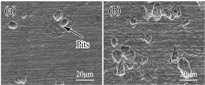
SOURCE: Chen et al. (2021).
increased in the presence of SRB. Additionally, some pits in inoculated samples were connected to form clusters. In the absence of SRB, the maximum pitting depth was 2.32 ± 0.2 μm, while the maximum depth in the inoculated sample was 6.01 ± 0.6 μm. Despite decades of effort to identify diagnostic fingerprints for MIC, most investigators agree that although certain morphologies are consistent with microbially influenced chemistries, MIC cannot be diagnosed solely by the morphology of localized corrosion (Eckert, 2003; Little et al., 2020).
Iron-Reducing Bacteria
IRB can be either strict anaerobes (e.g., Geobacteraceae) or facultative anaerobes that can use oxygen but can also derive energy from the reduction of other electron acceptors (e.g., Fe3+) under anaerobiosis (e.g., Shewanella sp.). Fe3+ is an efficient electron acceptor, and both anaerobes and facultative anaerobes are able to remove iron oxides from steel in laboratory experiments (Kappler et al., 2021).
Acid-Producing Microorganisms
Specific microbial metabolisms can produce inorganic (e.g., sulfuric) or organic acids (e.g., acetic). The corrosion rate of plain carbon steel in water does not vary with pH values between 4.5 and 9.5 (Coburn, 1978; Uhlig and Revie, 1985), but the activities of acid-producing microorganisms can cause the pH to drop to below 4.5 at the biofilm–metal interface. Under these conditions, protective iron oxide scales dissolve. Gu (2014) concluded that a pH 2 acetic acid solution was much more corrosive than a pH 2 sulfuric acid solution.
Sulfur-oxidizing bacteria (SOB) and archaea can oxidize reduced sulfur species (e.g., sulfides, sulfites, thiosulfates, polythionates, and elemental sulfur) to sulfuric acid. These microorganisms are extremely diverse, both ecologically and taxonomically. Most important, they are multifaceted with respect to the physiology and biochemistry of sulfur oxidation processes, exhibiting different abilities to use specific reduced sulfur compounds as substrates. SOB and SPP are ubiquitous in most soils and are responsible for sulfur cycling. Sulfur cycling has been demonstrated in biofilms and is cited as the mechanism for accelerated low-water corrosion of carbon steel in coastal marine environments.
APB are facultative microorganisms that can produce organic acids through a process of fermentation. Fermentation is a primary means of producing energy by the degradation of organic nutrients anaerobically. Pope (1990) conducted a study of buried steel gas pipelines and concluded that APB were more important to the corrosion than SRB. Gu (2014) reported that APB produced “alarmingly large amounts of organic acids.” However,
the precise role of APB in MIC is controversial. Pope et al. (1988) and Gu and Galicia (2012) concluded that the acids produced by APB were aggressive to plain carbon steel. In contrast, Mand et al. (2014) reported that the contribution of APB was to provide nutrients for SRB growth. In a field survey, Li et al. (2001) concluded that the maximum corrosion rates were measured when SRB were colocated with APB.
Filamentous fungi, ubiquitous in oxic soils and well known for their ability to convert organic material into organic acids, are not typically cited in the corrosion of buried steel. In general, fungi acidify their microenvironments, including soils, by excreting protons, organic acids, and CO2 (Gadd, 2010). Soil acidification can contribute to mineral weathering (nutrient cycling) and influence biofilm formation.
Methanogens
Methanogens are archaea capable of producing methane as a metabolic by-product under anoxic conditions. Numerous studies have documented methanogens in corrosive biofilms (e.g., Zhou et al., 2020), and methane formation has been correlated with metal weight loss of steel (Vigneron et al., 2016). However, methane does not react directly with steel. Multiple mechanisms, reviewed by Vigneron et al. (2016), have been proposed for the role of methanogens in corrosion of steel. Proposed mechanisms appear to be characteristic for some lineages but are not widespread among all methanogens and are similar to those suggested for SPP. For example, some methanogens reportedly couple methanogenesis with direct uptake of electrons from Fe0 (i.e., iron oxidation). Extracellular hydrogenases generated by some methanogens may be involved in the consumption of hydrogen generated by CO2 corrosion. Corrosion may be related to sulfidogenic dissimilatory sulfur reduction in S0-rich environments. Additionally, methanogens can contribute indirectly to MIC through interactions with syntrophic APB.
RELATIONSHIP BETWEEN CORROSION AND THE ENVIRONMENT
As described in Chapter 2, there are limited long-term in situ experiments on corrosion of buried steel. Many uncontrolled variables in the most well-known experiments (Logan, 1945; Romanoff, 1957) influenced corrosion rate. The resulting scatter of the data obscured any differences in weathering among the eight alloys tested; that is, the differences in corrosion of the different alloys was not resolvable due to the impact of environmental conditions and the fact that no significant difference could be identified between alloys (Logan, 1945; Romanoff, 1957). Additionally, in a comprehensive review of corrosion of steel in mechanically stabilized earth wall construction, King (1977) acknowledged that all ferrous metal is susceptible to corrosion but that “soil type is the dominant factor in corrosion rather than the type of steel.” More recent statistical analysis of the Romanoff (1957) data with linear and multiple regression confirmed that differences in the corrosion of the bare steel and wrought iron (low-carbon) were not identifiable as a function of soil type, stating that “scatter in the measurements resulting from the exposure variables and the natural stochastic nature of underground corrosion overwhelms any differences due to alloy type for this range of alloy compositions” (Ricker, 2010). Despite the fact that the experimental data have a large degree of scatter, these studies indicate that the rate of corrosion is controlled less by the type of steel and more by the physical, chemical, and microbiological properties of the environment in which the steel is buried. Consequently, the variability of the soil and environmental factors, when measured over scales that range from centimeters to meters to kilometers and years to decades, is of primary significance. Given the heterogeneity of the subsurface, the fact that alloy type is a secondary factor in corrosion is not surprising.
It is important to note that the Romanoff (1957) data were based on steel alloys that were available in the early 1900s, and steel design has changed significantly since. It is reasonable to assume that research and development of new alloys could change the types of steels used commonly in practice if steels could be developed that are less susceptible to corrosion, while still being economical at scale. However, because the inherent variability of the parameters of the electrolyte (e.g., soil and moisture) has, to date, obscured any differences between steel types, future studies will benefit from significant focus on the environment, not the alloy. Statistically designed experimental studies with thorough characterization of the soil, moisture conditions, and seasonal variability in climate may allow more sensitive identification of the differences in corrosion rates between different steel alloys, but until those data are available, the type of steel is a secondary consideration in corrosion.
This page intentionally left blank.


