
4
Technological Readiness
NIF LASER TECHNOLOGY
The proposed NIF rests on the progress in solid-state lasers that started with 1-J pulses from the Ruby laser in 1960 and extends to the present 40-kJ-level output from NOVA. This 40,000-fold increase in some 30 years is based on progress in the fundamental understanding of laser-host materials, on optimizing laser architecture for energy extraction, and on mitigating nonlinear effects that reduce beam quality and limit beam peak power. The NIF laser driver was proposed and designed to ignite a target by providing more than 1 MJ of pulsed energy at 350 nm. Further, the laser source is to be a reliable tool for laser-target studies, with adequate flexibility to control such important parameters as pulse shape, spectral properties, spatial smoothing, and pointing. The proposed NIF laser is based on a new architecture that reduces the number of optical elements, reduces the volume, and enhances the control and operational capability through a design that allows repair of laser beamlines between shots.
To test these advanced concepts, a single laser beamline, called the Beamlet, was constructed. The Beamlet has been operational since 1994 and has provided a test bed for the NIF architecture and design, including operation at the fluence levels of the NIF laser. It has proven the multipass oscillator/amplifier concept and shown that the potassium dihydrogen phosphate (KDP) plasma electrode polarization switch operates as expected. The Beamlet has also demonstrated the use of a diode-pumped fiber laser oscillator as the master oscillator for the more complex 192-beamline NIF, stability against small-scale self-focusing through relay imaging and spatial filtering, the advantages of an active mirror to control wavefront quality, and high nonlinear frequency-conversion efficiency for third-harmonic output at 350 nm.
NIF Laser Design Goals and Ignition Requirements
The NIF laser (Figure 2) has a design peak performance of 2.2-MJ at 600-TW peak power. It consists of 192 beamlines, arranged into four arrays. Each array is composed of 4 × 12 segments, each with an aperture of 40 × 40 cm2. The baseline operation is set at 1.8 MJ and 500 TW, at 350 nm. The NIF design was selected from two conceptual designs based on multipass architecture. An original 240-beamline design was deferred and the current design with 192 beamlines was selected as a compromise, based on a reasonable expectation of reaching ignition with the lower energy and power and associated cost trade-offs.
The NIF baseline design has a laser architecture selected to meet the required performance levels at acceptable cost while respecting the limits imposed by laser fluence damage. Peak fluence from a 4-pass amplifier through the optical beam path to the KDP harmonic-conversion crystal remains below the damage fluence of the optical elements, if they are procured from the highest-quality fabrication. The baseline design uses lower-cost components that can be more readily mass produced but have yet to meet the required damage thresholds. Optical damage can limit laser performance and facility reliability and is further discussed below.
The NIF laser performance goal was based on extensive target studies using the NOVA facility and studies at the Nevada Test Site. The latter tests, in the 1980s, proved the concept of ICF. That result, coupled with laser/target-interaction studies and computer simulations, determines a probable ignition regime in a peak-power vs. total-energy plot (Figure 3). The regime is bounded above by laser-plasma instabilities and below by hydrodynamic instabilities. A selected target design and predicted ignition point are shown. Figure 3 also shows the baseline and maximum safe-operating levels of the

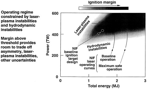
Figure 3 Target ignition regimes plotted vs. peak power in terawatts and peak energy in megajoules. The laser plasma and hydrodynamic instability regions are indicated. An ignition target design is indicated along with the National Ignition Facility baseline and maximum safe operating power-energy curves. Source: Lawrence Livermore National Laboratory.
NIF. The NIF laser design provides an estimated factor-of-two safety margin above the estimated ignition threshold.1
Beamlet Performance as Validation of the NIF Design
The NIF laser will operate with larger optics than any previous laser system. Figure 4 shows schematics of the NIF and the Beamlet laser designs. The two designs are substantially similar, with minor differences in the size of the optical components, the injection into the 4-pass laser amplifier, and turning mirrors between the NIF laser and the harmonic converter. Figure 5 shows the comparison of the Beamlet performance and the expected NIF beamline performance at 1050 nm. The Beamlet operates over the peak power/pulse-energy region projected for the NIF,2 with recent experience demonstrating the expected performance. The Beamlet has operated at the intensity/output-fluence levels projected for a NIF beamline, for pulses from 1 ns to 10 ns, and has exceeded the nominal NIF operating point.3


Figure 5 Comparison of the Beamlet and the NIF performance levels.
Source: Lawrence Livermore National Laboratory.
Performance, Cost, and Optical Damage
With cost strongly dependent on the maximum allowed optical fluence of components along the laser optical beam path, the NIF laser is designed to operate at the maximum fluence consistent with reliability and projected performance. Further, significant efforts have been made to raise the fluence-damage threshold of the optical components, to increase laser performance, and to reduce cost. Improvements have been made and the NIF is expected to operate at a fluence level approximately twice that of NOVA. The component nearest the damage fluence limit is the KDP tripler crystal, which becomes the ''fuse" of the optical train. Efforts are continuing to improve the damage threshold of this component, although it already exceeds the NIF requirement of 17 J/cm2, with measured damage thresholds between 17 and 25 J/cm2 at 350 nm in the highest-quality crystals, which are slow-grown using the most expensive technology. If the mass-produced KDP crystals from the lower-cost, rapid-growth technology currently under development do not meet the damage threshold requirement, the more expensive and time-consuming process will be used and can be accommodated within the current schedule and cost contingencies.
A program has been instituted to work with optical component vendors to further increase damage-fluence values by improving finishing methods. However, damage is a probabilistic phenomenon, initiated at the atomic scale or by bulk or surface impurities. Thus, future improvements in damage fluence cannot be predicted, and the prudent design should recognize the measured damage limits and operate within that constraint. The NIF laser has been designed to operate below proven damage levels of the optical components in the beamline path.
Laser Architecture
The NIF laser design utilizes a master oscillator-preamplifier, followed by a 4-pass amplifier with a polarization switch, followed by a booster amplifier. Compared to the NOVA linear-amplifier, this architecture has the advantages of compact design, fewer optical components, and reduced optical fluence along the beam path. The Beamlet laser was constructed at the scale of a NIF beamline to test the multipass amplifier architecture and the components of the NIF laser in a nearly full-scale system.4
Master Oscillator—Preamplifier
The master oscillator must be flexible in both wavelength generation (for bandwidth control) and in pulse-width generation (for temporal pulse shaping). Since 192 master oscillators are required for the NIF, followed by 192 preamplifiers to boost the energy to the near-10-J level prior to injection into the multipass amplifiers, a diode-laser-pumped master oscillator concept was selected as the master-oscillator design for the NIF.
The Beamlet master oscillator (MO) incorporates optical elements similar to those that would be used in the NIF MO. The Beamlet MO uses a diode-pumped laser, followed by an integrated optical modulator and a high-gain regenerative amplifier to provide output energy in a spatially and temporally controlled pulse shape. This MO output is then amplified in a flashlamp-pumped Nd: glass multipass preamplifier. The Beamlet MO has demonstrated the required pulse-shaping capability. It has also demonstrated bandwidth control capability by the generation of multiple wavelengths.
The experience with the Beamlet MO should reduce the risk for the NIF MO implementation, which is based on a diode-laser-pumped Yb:glass fiber-ring oscillator, followed by a regenerative amplifier and 192 10-J preamplifier modules. The NIF preamplifier is a flashlamp-pumped Nd:glass slab-geometry laser, with 4-pass amplification of the input waveform. The alternative of using a diode laser to pump the preamplifier was investigated, but the high cost of laser diode arrays currently prevents their use.
Multipass Amplifier-Booster Amplifier
A multipass amplifier using polarization switching and a 4-pass geometry was selected to reduce cost and yet provide the required energy with proper spatial and temporal beam shaping. Further, the amplifier design allows flexibility in the spectral content of the beam (both for SSD and for spectral chirping followed by compression to achieve higher peak power). Figure 4 shows a schematic of the 4-pass amplifier, as implemented on the Beamlet and as proposed for the NIF. The advantages of the multipass design include the need to purchase fewer of the largest optical components than in a traditional single-pass MO power amplifier design. The multipass amplifier design, however, requires the development of a large-aperture Pockels cell electrooptic switch that has good hold-off to prevent preoscillation and has high switching efficiency to maintain overall laser efficiency.
Injection
The 10-J preshaped input beam is injected through an aperture at the focal region of the vacuum spatial filter. Temporal and spatial preshaping is required to obtain the flat-top super-Gaussian output profile from the amplifier. The input beam is reflected from a deformable mirror that presets the wavefront to counter beam distortion in the 4-pass amplifier. In the Beamlet, injection takes place in the oscillator spatial filter. In the NIF, injection would take place prior to the booster amplifier to exploit the gain of the booster amplifier and to use the deformable mirror to correct distortions created by the booster amplifier.
The input beam is shaped in time to counter the effects of the amplification, in which the amplifier saturates for efficient energy extraction. Thus, the power of the input pulse rises in a carefully
controlled manner over a period of nanoseconds. The result, following amplification, is a shaped beam that meets the temporal target-illumination profile goal. The input beam is also spatially shaped to counter the higher amplifier gain at the edges compared to the center; the input beam to the amplifier has higher power around the perimeter to give a flat-topped beam after amplification.
Amplification
The amplifier consists of Brewster-angle glass-gain elements pumped by flashlamps. The main amplifier has 11 slabs, and the booster amplifier has 5 slabs, with a glass volume of 12 liters/slab. The Beamlet stores 35.65 kJ of energy in its main amplifier and 15.97 kJ in its booster amplifier. The amplifier is operated at an extraction beam to amplifier slab area ratio, or apodized "fill factor," of 90%; the NIF beamline design calls for operation at a fill factor of 94%.
Spatial-mode Filtering
The peak output power of the multipass amplifier is limited by changes in the induced nonlinear index of refraction. These changes can lead to small-scale self-focusing and peak intensities that exceed the dielectric strength of the optical components. Relay imaging, coupled with spatial filtering, has been developed to counter the onset of self-focusing. Measurements and modeling of these phenomena have agreed, giving the designers confidence that small-scale self-focusing can be prevented under normal operating conditions.
Pockels Cell Switch
The 4-pass amplifier geometry is critically dependent on a large-aperture Pockels cell switch. The Pockels cell optical switch consists of a KD*P (deuterated KDP) electrooptic element within the laser resonator. The KD*P switch rotates the plane of polarization of the laser beam to provide for additional passes through the amplifier, prior to switching the polarization direction for output coupling from the dielectric-coated polarizer. The successful development of the plasma electrode Pockels cell (PEPC) KD*P switch has allowed the 4-pass amplifier to move to the experimental-demonstration phase. The KD*P switch meets the optical-switching-efficiency goal of greater than 99.5%.
Deformable Mirror
The operation of the Beamlet line shows that the lamp-pumped slab amplifiers are the largest source of wavefront distortion. The distortion (beam-wavefront curvature and tilt) is induced by the thermal loading of the slab following pumping by the flashlamps. In the Beamlet, the beam distortion is controlled by presetting a 23-element deformable mirror prior to each shot. In the NIF beamline, the deformable mirror would be placed at the back mirror reflector position of the 4-pass amplifier and would be 40 × 40 cm2 in area.
Harmonic Generation
The technology for harmonic conversion using Type I second-harmonic generation, followed by Type II sum-frequency generation to the third harmonic output, is being applied to the NIF laser. KDP crystals required for the NIF frequency conversion are being grown both by a rapid-growth technique (which has not yet produced crystals meeting the NIF damage threshold requirements) and by the well-developed traditional solution growth approach. Experiments using the Beamlet have confirmed the conversion efficiency of the KDP crystal arrays. As mentioned above, the fluence incident on the KD*P harmonic converter is just below the damage threshold such that the KD*P crystal acts as the optical fuse in the NIF-beamline system.
Related Laser Experience
The LLE operates the OMEGA laser system. The laboratory has explored direct-drive target physics with the goal of determining whether the NIF has the potential for ignition via direct drive. Direct drive places tight tolerances on the laser system in beam smoothing, power energy balance, and beam temporal shaping.
Approaches to laser-beam smoothing were explored at the Naval Research Laboratory (NRL) 1983, using induced spatial incoherence (ISI). Beam smoothing by spectral dispersion (SSD) was explored at LLE in 1989. Together, these two techniques can control the laser beam at the target, providing a time-integrated smooth beam that reduces plasma instabilities for indirect drive and reduces laser imprinting on the target for direct drive.
The ISI approach to beam smoothing has been demonstrated on the broadband KrF NIKE laser at NRL. The broadband laser source gives rise to a change in the speckle pattern for a time inversely proportional to laser bandwidth. SSD uses diffraction to spatially translate different frequency components of the laser beam. Again, the speckle pattern changes with a time proportional to the inverse bandwidth of the laser source. Beam smoothing by SSD is better suited to solid-state lasers. An extension of SSD uses gratings in both directions transverse to the beam-propagation direction. Two-dimensional SSD has been demonstrated by the OMEGA laser system. The triple-frequency laser beam was made spatially homogeneous using a continuous digital phase plate, or kinoforrn phase plate (KPP). The two-dimensional SSD was demonstrated in the ultraviolet to provide beam smoothing. The technology for KPP generation, using 16 level phase steps, should meet the focal plane requirements on the NIF beam.
TARGETS
ICF targets are designed in accord with a detailed experience base, augmented by extensive simulation calculations that integrate, to the extent feasible, all aspects of the ICF process:
-
Laser pulse energy, including frequency, temporal, and spatial characteristics;
-
Hohlraum. geometry, materials, gas-fill (if any);
-
Target design, fabrication specifications, suspension system; and
-
Diagnostics integration.
Actual target fabrication relies on specialized technology and capabilities whose realities and limitations define a large number of the challenges of the ICF program. A baseline target design is in place and was used to determine the necessary operating parameters for the NIF. Possibilities for new and better targets, which would increase the likelihood of ignition, are being explored with the aid of recent advances in computational capabilities and related experiments. New ideas are being proposed regularly, including "cocktail" walls, different shapes for hohlraums, and new materials for capsules. The possibility that new and better targets might be developed before actual NIF operation in 5 or more years should not be discounted.
Hohlraum Design and Fabrication
In indirect drive, the irradiated capsule is placed in a thin, high-Z hohlraum, whose interior absorbs the laser irradiation and confines the x-ray irradiation field that heats and ablates the outer capsule layers, driving the implosion. Hohlraum designs have evolved to accommodate multiple-ring laser illumination in order to enhance the uniformity of energy deposition on the targets. A gas-fill option is intended to mitigate stagnation of ablated wall material on the hohlraum axis, and specialized designs can accommodate a host of diagnostics. At this writing, progress and technological readiness in this area are good.
Hohlraum designs are expected to evolve and be tested to accommodate the anticipated extension to cryogenic target capsules. Even though they are not part of the NIF baseline target design, future design and fabrication work may well explore noncylindrical hohlraum geometries (e.g., tetrahedral) that might produce greater uniformity in the capsule drive. Such geometries could be explored in the 60-beam OMEGA facility, which provides a laser-illumination field intermediate between the present 10-beam NOVA and the proposed 192-beam NIF.
Capsule Fabrication
Capsule design and fabrication specifications are closely related to the expected dynamics of the various hydrodynamic instabilities during the implosion phase, with trade-offs between required laser-irradiation, hohlraum, and capsule-fabrication specifications. In particular, capsule-fabrication specifications depend on the capsule design, material properties such as density uniformity, and surface-finish spectra (an initial amplitude is more serious in some modes than in others), and the irradiation field. Generally, doped-CH ablator shells require surface finishes of some 20 nm rms (for mode numbers >10) and can accommodate surface roughness up to 500 nm rms in lower modes. The HEP 4 experiments on NOVA used these specifications as a baseline. The technology for NIF-scale target fabrication is currently under development. Surface-finish specifications for beryllium ablators are estimated to be typically 2 to 3 times more forgiving. The fabrication technology for beryllium ablator shells, however, is not as advanced as that for plastic: either small fill holes, or seams between hemispherical capsule segments, or other means that would provide some material porosity are required for the deuterium-tritium (DT) fill. Issues of material-density uniformity also arise, depending on the materials and fabrication methods employed, and are still under study and development. 5
Although not all issues have yet been resolved, continuing experiments and simulations are expected to further define fabrication specifications. Given the evolution of the scientific understanding of hydrodynamic instability dynamics and the coupling between drive uniformity and capsule fabrication specifications, continuing progress in this area will increase the likelihood of achieving ignition on the proposed NIF.
Cryogenic Capsule Technology
Present NIF capsule designs include a high-density (solid), cryogenic DT fuel layer inside an ablator shell, containing a gas-phase DT core. Three important technology issues are currently outstanding. The first is related to the assembly/fill mechanics and resulting solid/gas surface finish. Interfacial-surface smoothness to about 1 μm has been demonstrated with beta-layering.6 The second is related to the mechanics of handling such capsules, from fabrication to installation in the target chamber, and laser irradiation. The third concerns methods for characterization of the fuel (compositional and physical uniformity) in optically opaque capsules (such as those fabricated from Be). A program is under way to address the first of these, and the second is now under consideration.
Such cryogenic targets are in an advanced stage of development because they will be required at the OMEGA laser within the next few years. While the deployment at OMEGA cannot be identical to that proposed for the NIF, invaluable experience will be gained before final NIF engineering is necessary. Although it is reasonable to expect that the target uniformity required will be achieved when it is needed, targets are of such great importance for the goals of the NIF that the progress in target fabrication should continue to be encouraged and monitored.
DIAGNOSTICS
The present suite of ICF diagnostics is the result of an intense and creative 25-year effort that proceeded in relative isolation because of both classification and the unique high-energy-density environment involved. Measurements enabled by these diverse diagnostics have played indispensable roles in tests of various kinds, in support of SBSS and ICF technology development, in experiments that probe fundamental ICF physics, and in code-validation experiments. A commitment to the continuing development of this component of the ICF program is crucial to the success of the NIF and SBSS.
ICF diagnostics can be grouped into three broad categories: laser characterization, hohlraum characterization, and capsule performance. These three classes may be further categorized as facility-provided and experiment-specific. Most diagnostic modules conform to standard mechanical, electrical, and data interfaces, and many can be used on either the NOVA or the OMEGA facilities. A similar philosophy of design standardization has been adopted and should be encouraged for the NIF and, indeed, at comparable facilities now being planned outside the United States.
Laser characterization diagnostics are used to measure such attributes as laser pointing, focusing, synchronization, temporal pulse profile, and back-scattered light. Hohlraum diagnostics are used to measure the history of hohlraum temperature and the spatial symmetry of the radiation drive. Some of these have also been used in experiments conducted at other ICF facilities. Capsule diagnostics have benefited from a variety of developments. These include a gating technology for micro-channel plates that allows nearly continuous, time-resolved (~50-ps intervals), two-dimensional x-ray imaging of imploding capsules. Such high-speed gating has reduced motional blurring of imaged ICF targets. Areal density images with high spatial resolution (~10 μm) and temporal resolution (~100 ps) can also be recorded using customize x-ray backlighting, which exploits a host of backlighter materials to vary the x-ray spectrum and can be timed, as necessary, through independent control of the backlighter beam(s). High-density plasmas can be imaged and diagnosed using x-ray laser interferometers.
Some nuclear diagnostics are currently in use, and others are being developed. These are necessary to probe the behavior of the capsule-core region and, as ignition is approached, to provide data from imploding capsules. Present and planned ICF capsule diagnostics are designed to record such quantities as neutron yield (63Cu activation), fuel-ion temperature (neutron time of flight), ignition time and fuel-burn history (fusion neutrons or γ-rays), imploded core image (neutron imaging), fuel areal density and implosion symmetry (tertiary neutrons or protons), and time-resolved fuel ion temperature (n-p recoil). Other diagnostics are also under consideration, such as a γ-to-Cerenkov conversion technique for burn-history measurements.
Despite the generally healthy state of diagnostics, many challenges remain. Further developments will be necessary to support the drive tuning (pointing, timing, and pulse shaping of the laser beams) necessary to achieve ignition on the NIF. Also needed will be diagnostics to characterize time-dependent radiation drive uniformity within the hohlraum volume, and to image with better spatial (5-10-μm) and temporal (<20-ps) resolution. New technology for post-ignition diagnostics that can survive the resulting harsh environment (debris, electromagnetic pulses, radiation) on the NIF will also be needed.
Multidimensional data-acquisition and imaging techniques (e.g., multiaxis tomography) can be expected to provide new types of data and should continue to be developed. Progress should also be encouraged in replacing photographic film with imaging detectors that have better efficiency, linearity, and dynamic range. Diagnostics to probe two-and three-dimensional unsteady hydrodynamics, developed both for ICF and other applications, will yield new data that will both advance understanding and validate simulations of these phenomena. The latter is particularly important, in view of the extension of numerical simulation capabilities enabled by the emerging ASCI machines.
The development of ICF diagnostics will be coordinated by the Joint Central Diagnostic Team formed among the National Laboratories. This group is charged with defining requirements, selecting and developing diagnostics, and integrating the diagnostics into the NIF program. Each laboratory will
have lead primary responsibilities funded under its ICF program funds. Other research groups are also contributing to this effort, as the community of ICF-facility users further expands to universities.
THE NATIONAL IGNITION FACILITY PROJECT
Project Organization
The NIF project organization and its relationship to the LLNL appear to be sound and acceptable. In place are the elements that are critical for optimizing the chances for successful project implementation and completion, including the following:
-
The project has support from DOE management. There is a clear chain of command as well as a method of appeal to address problems and break logjams, with laboratory management fully committed to the project.
-
At the start of the Title I process, the work breakdown structures and project organization structure were in place and aligned to provide clear technical interfaces. This structure was tested during the Title I process.
-
The project manager has sufficient administrative autonomy to accomplish work in a timely, efficient manner. This includes a $25 million procurement authority that resides at LLNL to facilitate the procurement of necessary items with a minimum of red tape. The procurement authority alone is a significant step. In addition, a number of procurement specialists have the NIF as their first priority. The dedicated legal support available to the project is also helpful.
-
The project is led by an appropriate number of competent project leaders and engineers. This leadership will facilitate good and frequent communication among the leadership team and allow issues to be dealt with effectively.
-
Twenty-eight design basis books describe in detail all the special equipment items to be built. Interface control and a Baseline Change Control Board are in place to maintain the integrity of scope, cost, and time line.
-
There is a project tracking system commensurate with a maximum expenditure rate of about $20 million per month. This tracking system is quite detailed, with the project broken into procurement packages. There are cost accounting plans with schedule milestones that allow close monitoring of progress based on completed activities. The relatively large number of milestones to be measured allows an objective assessment of progress.
-
The project leadership has a good relationship with both DOE Oakland and DOE headquarters, a prerequisite for effective project management. That relationship will prove essential in resolving any unanticipated variances about the original scope, cost, and time line.
Title I Review
Based on the design basis books and the interface controls in place, a preliminary design (Title I) was done, and LLNL formed a number of committees to conduct a review; these committees include both internal and external experts. The review was a complete and stringent process involving 96 professionals with expertise in all of the relevant areas (facility expertise: 20 members; laser system expertise: 38 members; target area expertise: 18 members; systems control expertise: 9 members; optics expertise: 5 members; and operations expertise: 6 members). The results of this Title I review are now the baseline for the project and are reflected in the Schedule 44 for FY98.
Cost Estimates
To date there are two complete independent cost estimates (ICEs) for the NIF project: the 1994 estimate based on the preliminary design (reflected in the Schedule 44 for FY97), and the 1996 estimate based on the results of the Title I review (reflected in the Schedule 44 for FY98). The total estimated cost (TEC) of the original project remains the same within the uncertainty of the estimating methods. However, the FY96 cost estimate includes an additional $29 million for site-specific costs and $125 million of additional scope compared to the 1994 estimate, resulting in a net increase of $154 million. However, the TPC has increased by only $74 million, because the start-up costs (and the scope of work associated with them) have been reduced from $77.5 million to $7.1 million. Most of the start-up costs have been moved to the LLNL-projected operating budget for NIF and NOVA operations. In addition, there are NIF-related non-TPC costs of $397 million in LLNL-projected operating funds in FY98-FY02. The contingency has also been reduced from S $144 million (20.6%) to $127 million (14.6%). In addition to the TPC, non-TPC funds of $120 million (FY98-FY02) are planned for R&D in optics and laser technology. LLNL plans to use these funds to perform R&D and to qualify vendors to the point that a 14.6% contingency becomes acceptable.
The start-up funding in the FY96 cost estimate of $7.1 million within the TPC is sufficient to test one bundle of lasers (4% of the full facility). The remaining start-up costs necessary are included in the NIF portion of the NOVA/NIF operating costs ($175 million in FY99-FY02). To make these funds available to the NIF presupposes that NOVA operations are shut down, curtailed greatly, or supported from other sources at the end of 1998, which may hinder the pursuit of the remaining hurdles discussed in Chapter 5.
The operating budget for the target physics program includes diagnostics and instrumentation not included in the TPC, as well as other items such as modeling. Of the $155 million projected for these activities (FY99-FY02), about $102 million appears relevant to the NIF. The committee notes that these are LLNL/NIF projections of additional operating funding.
In summary, the projected costs relevant to the NIF through construction consist of the TPC at $1.148 billion, with additional non-TPC costs in the LLNL-projected operating budget: $120 million for optics and laser R&D, $102 million for diagnostics and instrumentation, and $175 million for start-up costs and other R&D.
Independent Cost Estimate Review
An independent cost estimate review was contracted by DOE headquarters to Foster Wheeler, a company that has no other responsibility in the project. An ICE with contingency was completed in 1994, as reflected in Table 3. The committee notes that the TPC of 1994 did not include any site-specific costs; $29 million must be added to the 1994 TPC to make it site-specific to LLNL. A second ICE review took place in 1996; the final report was pending at the time this report was drafted. The Schedule 44 FY98 TPC and the 1996 ICE review reflect the results of the Title I review and a more complete
Table 3 NIF Cost and Contingency Data (Actual $M)
|
|
Schedule 44 (FY97) |
ICE 94 |
Schedule 44 (FY98) |
ICE 96 |
|
TEC ($ M) |
843a |
834 |
997b |
|
|
TPC ($ M) |
1074a |
1034 |
1148b |
1150 |
|
Contingency ($ M) |
144 |
143 |
127 |
|
|
Contingency (%) |
20.6 |
20.6 |
14.6 |
19 |
|
a Site-specific costs need to be added, ranging from $29 million to $130 million, depending on the site. The LLNL site adds $29 million.) b Additional scope ($125 million) is included as discussed in the text. |
||||
Table 4 LLNL-Projected NIF-Related Funding
|
FY98 ($ M) |
FY99 ($ M) |
FY00 ($ M) |
FY01 ($ M) |
FY02 ($ M) |
Subtotal |
NIF Related Total ($ M) |
|
Additional non-TPC funding (Operations, NOVA, and NIF) |
||||||
|
|
30 |
40 |
50 |
55 |
|
175 |
|
Additional non-TPC R&D funding (optics and laser technology) |
||||||
|
40 |
40 |
20 |
10 |
10 |
|
120 |
|
Target-Physics Programa |
||||||
|
|
25 |
40 |
40 |
50 |
155 |
102b |
|
|
|
|
|
TOTAL |
|
397 |
|
a Includes scope (e.g., experimental diagnostic instrumentation) not included in TPC. b Assumes that two-thirds of the subtotal is relevant to the NIF. |
||||||
design. An additional $125 million in scope was added to the project between the 1994 and 1996 ICE reviews, including direct-drive capability, a radiation effects testing option, flashlamp cooling to increase shot rate, smaller spot size capability, and beam-smoothing capability.
Table 3 contains NIF cost and contingency data, and Table 4 gives LLNL projections of non-TPC funding available for technology development and R&D that is currently the mission of the ICF program and necessary for the NIF.
Contingency Analysis
A contingency of about 15% is adequate for conventional facilities. However, special equipment that requires a great deal of R&D, technology development, and vendor qualification carries a greater risk, so that 25 to 35% at this stage of the NIF project is more realistic. The present overall contingency rate of 14.6% thus seems low. However, in accord with ongoing funding received by LLNL for the laser technology development mission, the TPC has been defined more narrowly, with much of the necessary R&D covered in specific areas outside the TPC, as detailed in Tables 3 and 4. These additional funds projected by LLNL will advance the technologies and qualify vendors to the extent that a 14.6% contingency is self-consistent.
Operating Cost
High-technology facilities usually require between 10 and 13% of the TPC to fund operations each year after the facility is fully operational. For a TPC of $1.148 billion, the expected operating budget would be $115 million to $150 million. LLNL projects a NIF operating budget of $60 million, with an additional $60 million provided by the target physics program (NOVA, OMEGA, NIF) to cover some of the facility's experimental operation in FY03, for a total of $120 million to cover the facility's experimental operation in FY03.
Looking more precisely at the narrowly defined ''operating budget" (that is, without the target physics program contribution), NIF project personnel provided the committee with detailed documentation on the operating budget and the procedure used for the bottom-up collection of judgments on operating budget requirements from skilled practitioners on NOVA. Although the NOVA personnel are the best qualified people to do the bottom-up input, the NIF is a significantly larger facility than NOVA and the experience of the NOVA personnel may lead them to underestimate the operational complexity.
NIF project personnel also provided data on the NOVA operating budget as a percent of TPC. The initial operating budget for NOVA in 1986 was $10 million ($6 million for personnel and $4 million for consumables) or about 6% of the NOVA construction cost of $176 million in as-spent dollars. That NOVA operating budget corresponds to about $17 million in 1997 dollars, which is indeed the NOVA operating budget in 1996. The NOVA operating staff consisted of 28 professionals and 49 technicians in 1986 and consisted of 6 professionals and 56 technicians in 1996. The current NIF operating staff includes 260 people, which is consistent with the $60 million operating budget.
The committee notes that the apparently low proposed direct operating budget of $60 million appears compatible with NOVA experience, and that with the additional $60 million projected in the target physics program the total funds available ($120 million) are consistent with the 10 to 13% expected from experience of similar megaprojects.


