
2
Current and Future Needs
The demonstrated and potential characteristics of CMCs have excited sufficient interest to sustain research and development for more than 15 years. This long-standing dedication has been based on the hope of creating materials with chemical and environmental stability that approaches the stability of monolithic ceramics, but with sufficient toughness and strength for structural applications. If these goals are achieved, it is anticipated that CMCs could enable improved performance in several commercial and military applications. In this chapter, the current and projected requirements of ceramic fibers and interfacial coatings are discussed in the context of composite fabrication and end-use applications.
Fiber and interface (e.g., fiber coating) requirements are based on the performance requirements of CMCs, which are defined by the performance requirements of intended applications. However, translating application requirements to fiber and interface requirements is difficult for two key reasons:
-
CMCs are significantly different from monolithic ceramics, or even from fairly well understood polymer matrix composites (PMCs). The combination of limited ductility of the ceramic matrices and the highly aggressive environments in which they are intended to operate present notable challenges to defining constituent requirements.
-
Because of a general lack of field experience, a clear understanding of how CMCs will perform in service has not been developed. Without operational experience, it has been impossible to calibrate knowledge with analytical models of performance.
Nevertheless, three long-term imperatives facing the United States have sustained interest in CMCs. These are:
-
National Defense and Space Exploration. Aircraft, spacecraft, and missile structures and engines require more efficient (e.g., higher thrust-to-weight ratio), less detectable components.
-
Energy Efficiency. Expanding global industrialization will continue to put pressure on energy resources, heightening concerns about energy efficiency.
-
Environmental Regulations. Regulatory mandates to reduce emissions will continue to be an incentive for developing cleaner, more efficient combustion cycles.
CMCs show promise in addressing all of these imperatives because they are inherently refractory, have low density, and have demonstrated damage tolerance in some applications, suggesting that they could be used in light-weight, thermally loaded structures. CMCs also have weaknesses, however, such as oxidation embrittlement in non-oxide ceramics and limited creep strength in oxide ceramics. The useful performance attributes and weaknesses of CMCs are listed in Table 2-1. The advantages of CMCs over competing materials are most apparent when corrosion resistance is required or when benefit can be derived from reducing the cooling requirements of a component. Two examples are presented in Box 2-1.
IMPLEMENTATION OF NEW MATERIALS
The history of implementing new materials systems is littered with the remains of unanticipated failure modes encountered in service. For example, environmental effects and a general lack of understanding of the failures in carbon/epoxy fan blades devastated the early PMC industry in the 1960s. The effects of rain and sand caused significant erosion of the polymer matrices, and the inability of PMCs to survive
TABLE 2-1 CMC Performance Attributes and Weaknesses
|
Useful Attributes |
Weaknesses |
|
Notch insensitivity (high toughness) |
Low tensile strength (UTS) |
|
Scale insensitive UTS |
Very low interlaminar strength |
|
Some “ductility” |
Susceptibility of SiC to “pesting” (oxidation embrittlement) |
|
Low density |
Low thermal conductivity (oxides) |
|
Low thermal expansion (SiC) |
Limited creep strength (oxides) |
|
High thermal conductivity (SiC) |
|
|
Low thermal conductivity (oxides) |
|
|
High creep strength (SiC) |
|
|
Oxidation resistance (oxides) |
|
|
Low dielectric constant and loss tangent (oxides) |
|
BOX 2-1 Sample CMC Applications Turbine Shrouds The first stage shroud (see, for example, Figure 2-1) is exposed to some of the highest gas temperatures generated in a gas turbine engine. Current shrouds rely on coated nickel-based superalloys, which are air cooled. The material capabilities of these alloys limit the shroud temperature to approximately 920°C (1,688 °F), which requires the use of cooling air, resulting in a substantial penalty in efficiency. CMCs may satisfy the mechanical and environmental requirements, while at the same time substantially reducing the need for cooling air, resulting in improved engine efficiency. For example, by replacing a cooled metal shroud with  FIGURE 2-1 Cross section of the hot stage components of a large General Electric utility gas turbine. Source: General Electric Corporation. a CMC shroud in a 160 megawatt industrial gas turbine, a significant annual fuel savings could be realized. Combustion Liners Gas turbine manufacturers throughout the world are currently pursuing technology for reducing emissions of air pollutants in the exhaust. The most common pollutants generated by the combustion of conventional fuels are NOx, CO, and unburned hydrocarbons (UHC). Lean premixed combustion is a promising method for reducing emissions. Burning the fuel after premixing with excess air is particularly effective at reducing the thermal NOx, which is formed by oxidation of molecular nitrogen in the air at a high flame temperature. Excess air in the reaction zone of the combustor acts as a heat sink that lowers the flame temperature to the point where oxidation of nitrogen proceeds too slowly to produce any NOx in the combustor. To reduce the flame temperature in the reaction zone below the NO x formation threshold, nearly all of the air available to the combustor must be premixed with fuel upstream of the reaction zone. If the combustion liner is film air cooled, as is necessary with conventional superalloys, the fraction of the combustor air not available for premixing with the fuel is 30 to 40 percent. Consequently, it is impossible to operate the combustor lean enough to remain below the NOx formation threshold. This problem could be solved using a CMC combustion liner that can withstand the temperature of the hot gas in the reaction zone without film air cooling. Using the available air for lean premixing rather than film air cooling would result in a reduction in NOx emissions. CO and UHC emissions could also be reduced because the hot surface of a CMC combustion liner could be operated at a temperature high enough to ensure that the fuel oxidation reactions were not quenched at the combustor walls, even if the mixture were lean enough to prevent thermal NOx formation. Source: DOE, 1993. |
impacts by foreign objects, especially birds, caused a safety/reliability problem that could not be overcome within the design requirements of the blades being considered. Experience with the early Comet aircraft in the United Kingdom (UK) and the F- 111 aircraft in the United States demonstrated that a lack of understanding of fracture toughness and crack growth behavior, and an inability to detect critical flaws could lead to problems, even when systems were designed with comparatively “well understood” metals for which large databases were available. Current knowledge about CMCs and their failure modes is based primarily on extensive laboratory data. These data, however, have not been validated by field experience—which incorporates combinations of effects unique to the operational environment.
Short development times, which are characteristic of the current manufacturing climate, have exacerbated the problem. Moreover, the complexity of CMC systems and the aggressive nature of the environments they must operate in have made the challenge of implementing them more difficult. Despite great progress in accelerated testing and computational modeling techniques, it is impracticable to simulate all possible scenarios.
For these reasons, it is imperative that intelligent, selective component, rig, and “in service” testing be performed to validate models and laboratory-based data. Although only a few examples of “in service” experience are available, they are instructive because each presents different combinations of materials properties and application experiences.
The use of glass and glass-ceramic matrices for CMC fabrication aroused considerable interest and support in the 1970s and 1980s. Efforts to commercialize this technology were unsuccessful, however, because the market base was too small and there were no viable commercial suppliers. Nevertheless, numerous gas turbine engine component demonstrations
were successful, and one component for the F-119 engine achieved bill-of-materials status in pilot plant production.
Recently, the Schott Corporation has set up a small plant in Germany that is producing glass matrix composite components for industrial applications. Their first implementation has been machine components for handling hot glass, and the company is beginning to expand its market.
SiC matrix composites have been under development since the late 1960s, particularly composites produced by melt infiltration (e.g., General Electric Corporation in the United States) and CVI (e.g., SEP and the University of Bordeaux in France) (Hillig et al., 1975). Laboratory data obtained in the mid-1970s and 1980s demonstrated high temperature stability and encouraged deployment of these materials. The system developed by SEP underwent extensive rig testing, which led to a flight demonstration of a SiC matrix composite engine nozzle at the Paris Air Show and, ultimately, investments in facilities to scale up production in SEP's M53, M88, and EJ-200 engine models. However, large scale deployment never occurred because of unanticipated environmental degradation of the SiC composite components. SEP's experience undermined confidence in these materials, even at this late stage of development.
Dornier of Germany developed oxide fiber-reinforced mullite matrix composite systems in the 1980s. The system was based on 3M's Nextel 312 fibers and slurry impregnation of a mullite matrix. This composite demonstrated modest levels of strength (120 MPa [17.4 ksi]) and low failure strain (0.2 to 0.3 percent). Several hot gas exhaust nozzles for Dornier's turboprop aircraft were successfully deployed and continue to be used in regular service.
An oxidation-inhibited carbon matrix material reinforced with carbon fibers was developed and tested several years ago by the Wright Laboratory Materials Directorate, Hitco, Inc., and General Electric (Aviation Week, 1993). This technology has since been developed further by the replacement of traditional carbon fibers with SiC fibers and the addition of a SiC overcoat. SiC is inherently more resistant to oxidation than carbon and, therefore, retains strength and durability for a longer period of time in service. The oxidation-inhibited carbon matrix offers stiffness—and in the absence of oxidation—remarkable high-temperature mechanical properties. The SiC overcoat protects the composite from oxidation, as well as from other environmental threats. Engine flaps and seals made of this material have improved operating life by 900 percent over metal components (Wright Patterson Materials Directorate, 1995). Thousands of GE-F414 engine hours have been accumulated using this system, and this experience will add valuable information to the knowledge base.
CERAMIC MATRIX COMPOSITE DESIGN AND LIFE PREDICTIONS
Focusing on the CMC applications with the greatest potential for implementation requires placing CMCs within the broad spectrum of thermostructural materials. CMCs differ appreciably from structural metals, monolithic ceramics, and PMCs in their thermomechanical performance. Consequently, the strategies that govern design and life predication for CMCs are unique. The following guiding principles should facilitate the successful implementation of CMCs in targeted applications:
-
Applications for CMC components should have loading and thermal profiles that exploit the attributes of the material; applications that are sensitive to the weaknesses of the material should be avoided (see Table 2-1).
-
Computational design and life prediction codes should be developed explicitly for CMCs. Computational models and predictions should be validated by subelement and component tests that include representative thermomechanical loadings. Rigorous analyses of failure modes should then be performed.
-
Designs and fiber architectures that obviate the delamination sensitivity of the critically important joints and attachments should be used (as they are in PMCs).
Because of their damage tolerance, CMCs perform well when they are subjected to thermal loads. However, because of their low UTSs, they are less robust upon inertial loading. Almost all of the applications envisaged for the near-term implementation of CMCs are, therefore, dominated by thermal loading requirements. The greater challenges of using CMCs in inertially loaded components should be deferred until field experience has been gained for thermally loaded components.
Because most CMC applications are dominated by thermal loads, the material temperature depends not only on the component environment (e.g., gas temperature in a turbine engine), but also on material properties and thermal boundary conditions. In a typical environment, material temperatures decrease as their thermal conductivity increases. Therefore, in common thermal environments and boundary conditions, SiC-based materials have lower material temperatures than oxides because of the higher thermal conductivity of SiC.
TABLE 2-2 Industrial Power Generation Applications
|
Program |
Country |
Application Type |
Components |
Typical Goals |
|
Land-based gas turbines |
United States |
power generation |
combustor turbine vanes |
1,600°C (2,912°F) for > 25,000 hrs |
|
100kW ceramic gas turbine |
Japan |
automotive |
combustor turbine vanes |
1,250°C (2,282°F) for 200 hrs strength 500 MPa (72.5 ksi) |
|
Continuous fiber ceramic composite program |
United States |
power generation |
shrouds combustors thermophotovoltaic power |
900°C (1,652°F) for > 25,000 hrs |
|
Continuous fiber ceramic composite program |
United States |
industrial processing |
chemical pumps radiant burners gas filters furnace hardware reforming tubes |
350°C (662°F) for 30,000 hrs in an environment containing organic and inorganic chemicals |
CERAMIC MATRIX COMPOSITE APPLICATIONS AND REQUIREMENTS
A range of applications have been identified that require the attributes of CMCs listed in Table 2-1. The material requirements are diverse but can be classified into two cross-cutting categories. The first differentiates applications based on use sectors, such as energy and aerospace (see Table 2-2, Table 2-3, and Table 2-4). The second is based on material durability requirements, which are derived from time and temperature profiles (Figure 2-2). The first category is useful because the energy sector could provide a large enough market to reduce fiber costs. Implementation in this sector is, therefore, crucial. The second category facilitates setting goals for fiber properties.
Energy Systems
A high market volume for a broad range of CMC components is more likely in the industrial markets (e.g., power generation) than the aerospace industry. Potential high volume industrial applications could create enough demand for CMCs to lower fiber costs significantly, which would make more cost sensitive applications possible. For example, ground-based turbine engines have less stringent weight restrictions than airborne systems, but they have more stringent cost requirements (e.g., automotive engines) and long-term durability requirements (e.g., land-based power generators). Several potential industrial applications for CMCs are listed in Table 2-2, along with the programs that support their development.
The following near-term, lower risk applications represent product insertions that could provide long-term experience with CMCs:
-
hot gas filters for pressurized fluidized bed combustion (PFBC) and integrated gasification combined cycles systems (IGCC)
-
furnace hardware, such as pipe hangers for petroleum refining
-
reverberatory screens in porous radiant surface burners used for drying, curing, and process heating
-
components for melting and handling metals
These near-term applications will probably not require using CMCs at the upper limits of their performance envelope (Figure 2-2). For example, experience is currently being gained with 3M's Type 203 ceramic composite filters (Figure 2-3), which are candle-type filters that consist of a SiC matrix reinforced with Nextel™ fibers. These filters are used to remove particulates from high-temperature (up to 1,200°C [2,192°F]) gas streams. Potential applications include PFBC, IGCC, and incineration. Lower risk applications like these are representative of the product insertions needed to gain long-term experience with CMCs.
Longer-term applications will be at a higher level of risk to end users who have performance requirements for higher temperatures and longer durations. The durability requirements of some industrial (energy) applications are shown in Figure 2-2. These applications include:
-
nonrotating components in stationary gas turbines, especially combustion liners and shrouds
TABLE 2-3 Aircraft Applications a
-
heat exchangers for externally-fired combine cycles (EFCC) power systems, in which the hot air is supplied by a coal-fired heat exchanger and which must operate at approximately 1,400°C (2,552°F) in a coal slag environment for tens of thousands of hours
-
thermophotovoltaic (TPV) power systems for household appliances (gas-fired hot water heaters and furnaces that operate in times of electrical outages) and quiet generators for the recreational market (recreational vehicles, yachts), in which a ceramic composite with selective emission characteristics excites matched photovoltaic cells and which must operate at 1,400°C (2,552°F) to achieve the required power densities
-
reforming tubes for the chemical processing industry
Aerospace Systems
Aerospace applications can be divided into aircraft, missile, and space systems. Several aircraft programs are focused on tailoring CMCs to improve performance, reduce weight, improve fuel efficiency, and reduce undesirable emissions from gas turbine engines. Some of these programs and their goals are listed in Table 2-3. In general, although the highest exposure temperatures are frequently quoted as “goal” temperatures, performance at lower temperatures and during thermal cycling may be more demanding.
In each case, the CMC components must have the following attributes for a predetermined time:
TABLE 2-4 Space Applications (United States)
|
Program |
Type |
Components |
Typical Goals |
|
Integrated high performance turbine engine technology |
missiles |
combustors turbine rotors |
operating temperature > 1,400°C (2,552°F) |
|
Integrated high payoff rocket propulsion technology |
space vehicles and tactical missiles |
turbomachinery thrust chambers nozzles |
very high temperature for short periods of time |
|
NASA reusable and expendable launch vehicles |
space vehicles |
thrust chambers nozzles thermal protection |
not available |
|
In-space propulsion |
satellites |
maneuvering thrusters |
operating temperature > 1,700°C (3,092°F) for < 10 hrs |
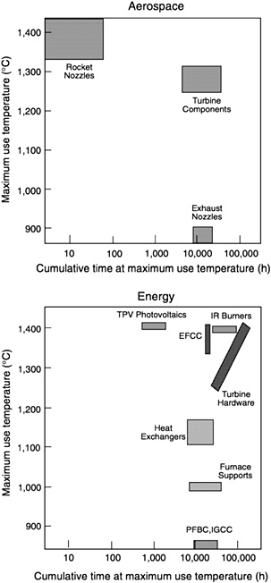
FIGURE 2-2 Thermal performance requirements for various high-temperature applications.
-
stability at the goal temperatures indicated and, during thermal cycles, through lower temperatures
-
resistance to chemical attack in the gas path flow
-
sufficient strength/strain capability to survive normal operating conditions and periodic instances of damage (e.g., overstress)
-
reproducible performance
Even though exhaust nozzles in aircraft engines represent a lower temperature, near-term application, the requirements

FIGURE 2-3 3M Type 203 Nextel fiber-reinforced SiC matrix ceramic composite candle filter. Source: 3M Company
for successful implementation are demanding because unprotected exposure to the atmosphere results in ingress/egress of atmospheric moisture (the same problem that plagued the early deployment of PMCs). The presence of matrix cracks in CMCs makes moisture flow possible. In military aircraft, there is an added requirement for low observability (e.g., low dielectric constant).
The implementation of CMCs in spacecraft and uninhabited vehicles is attractive because material life requirements are much less demanding than the requirements for aircraft and industrial applications ( Table 2-4). Because the operating environment in space is often non-oxidizing, life limiting oxidative embrittlement of non-oxide ceramics will not occur. Consequently, materials based on SiC and C are viable choices and have already been well established from the perspectives of performance and manufacturing characteristics. These limited volume high value applications could add to the production base of CMCs.
MANUFACTURING REQUIREMENTS
Reliability and Reproducibility of Fiber Supplies
One of the key features of emergent materials technologies is the constant changes in processing by materials producers to improve performance and lower costs. Unfortunately the ramifications of these changes are often subtle and cannot
always be anticipated. Changes in fiber property requirements and expansion to higher volume production, however, create constant pressure to improve productivity and, hence, to implement processing changes. At some point in the development of ceramic fibers, quality control measures must be put in place to identify and maintain a baseline process configuration (i.e., “frozen” in place). Overly restrictive quality control measures can stifle innovation, whereas uncontrolled process changes can lead to unanticipated performance degradation in end applications.
Handleability and Processability
CMC components have complex shapes, and because of their very low off-axis strength they require multiaxial fiber reinforcement. To attain such complex shapes, the fibers must be able to be readily handled. That is, fibers must be able to be bent through radii of a few millimeters. Furthermore, if coatings are applied to fibers before the final composite fabrication steps (e.g., filament winding, etc.) coating adherence and durability must allow bending, weaving, etc. Ceramic fibers are subjected to temperature extremes and unique environments during processing (Table 2-5). Obviously fibers are needed that do not degrade during exposure to composite processing environments.
IMPLICATIONS FOR FIBER PROPERTIES
Studying the temperature and time-at-temperature requirements for potential CMC applications (Figure 2-2) can provide a perspective on fiber property requirements. It should be noted, however, that material temperature is a function not only of the temperature of the service environment, but also of material thermal conductivity and engineered cooling strategies. Furthermore, fiber durability may not be dictated by property retention at the highest material temperature. For
example, non-oxide ceramic fibers demonstrate significant property retention at temperatures as high as 1,600°C (2,912°F). CMCs made from non-oxide fibers, however, have life limiting “pest” problems at intermediate temperatures (e.g., 700 to 900 °C [1,292 to 1,652°F]) under cyclic loading conditions in an oxidizing atmosphere.
Nevertheless, thermal requirements are useful for setting goals for the microstructural stability and creep resistance of fibers. For example, during component service life, grain growth at the highest use temperature should be less than approximately 20 percent in order to limit the attendant strength reduction to less than 10 percent. Fiber creep strain and creep rupture life must also be at acceptable levels. For example, fiber strains greater than approximately 1 percent are unacceptable because the attendant composite distortions compromise attachments, dimensional tolerance, etc. Defining fiber performance requirements for a temperature-time domain is contingent upon CMC component design—through the expected stress levels—as elaborated below.
General Considerations
The performance of thermally loaded components (in the absence of inertial loading) is dictated by thermally induced strain: eT= a?T, where a is the thermal expansion coefficient, and ?T is the temperature difference between adjacent regions of the component. The relationship between CMC failure strain (ef) and thermally induced strain (eT) can be used as a metric to rank materials for preliminary designs within regions subject to high thermal flux:
ef> eT (1)
The relationship between the strain at the proportional limit (ep, strain at which matrix cracking occurs) and eT ranks materials for general thermal loads:
ep > eT (2)
TABLE 2-5 CMC Processing Environments
|
Process Type |
Process Environment |
Maximum Temperature |
Time in Process (hours) |
|
Chemical vapor infiltration |
multiple inert and corrosive gases |
940 to 1,220°C (1,724 to 2,228°F |
100 |
|
Reaction bonding |
molten silicon |
1,450 to 1,500°C (2,642 to 2,732°F |
1 |
|
Polymer infiltration and pyrolysis |
various chemical infiltrants with ceramic powders |
800 to 1,200°C (1,472 to 2,192°F |
multiple steps with 100-hour total |
|
Directed metal oxidation |
molten aluminum |
950°C (1,742°F) |
100 |
Equation 1 can be used as a guide for fiber requirements, because ef is approximately equal to the strain-to-failure of dry fiber bundles (provided they are adequately protected against degradation during manufacture by appropriate fiber coatings and matrix infiltration technology). Equation 2 is dictated largely by the matrix.
CMC components are designed so that Equation 2 is satisfied over most of the structure. Similar to other thermostructural systems, however, local exceedences (e.g., eT > ep) are likely and are permitted in the design because the precise loads experienced during service are not known. Provided that eT does not exceed ef, composite durability should be adequate. If local exceedences create a situation that results in a reduction of ef (i.e., fiber degradation), however, durability would be compromised. For example, matrix cracking (eT > ep) in the presence of oxygen can create pathways for oxygen ingress and concomitant oxidative embrittlement of non-oxide ceramic fibers. Moreover, with thermal loadings, the largest tensile stresses occur in the cooler regions of the structure, where “pest” problems are most debilitating. Therefore, in addition to ef and ep, system approaches to limit the consequences of matrix cracking must be part of the design.
For composite applications, there are no explicit requirements on the ultimate tensile stress (UTS) of CMCs, although an implicit minimum UTS is dictated by stiffness requirements. Furthermore, there are no requirements for CMC toughness. Instead, the notch performance is more indicative of thermomechanical robustness (i.e., the reduction in net-section UTS upon notching the material). Notch performance is a benchmark for damage tolerance and can be used in the design of holes, slots, and attachments. Damage tolerance is controlled by the frictional characteristics of the interfaces, which is manifested in inelastic deformation. Good notch performance throughout a representative thermomechanical exposure is essential to the implementation of CMCs.
Fiber and Interface Requirements
Given the limited amount of field experience and the limited analysis of that experience, it is premature to be explicit about property requirements. Thermal loadings tend to be benign because inelastic strains redistribute the stresses caused by thermal expansion. Design calculations that do not take these stress redistributions into account can lead to overly pessimistic conclusions. Creep and rupture requirements cannot be directly related to fiber creep rupture diagrams (Chapter 3) because the stresses on fibers in thermostructural applications are unknown. Unlike thermal loads, pressure and inertial loads continue to act and cause strain accumulation throughout the operating cycle of a CMC component. Therefore, matching material properties to application requirements requires distinguishing between thermal and mechanical loadings. This distinction is rarely made in finite element computations.
Classifying applications by the maximum use temperature (Tmax) and the time (tm) at that temperature is not always relevant because life limiting mechanisms may operate at lower temperatures, thus negating high-temperature performance in medium-duration (e.g., aircraft engines) and long-duration (e.g., land-based power turbines) applications. Some applications (e.g., rocket nozzles), however, require very short-duration performance at extreme temperatures. Because the service environment affects the relevance of Tmax and tm, focusing exclusively on Tmax or tm is imprudent.
For robust thermomechanical performance, the toughness and ductility manifest in the notch behavior cannot be compromised. Presently, no guidelines have been established for setting requirements for these properties. Experience indicates that tensile “ductility” (i.e., fiber failure strain) that exceeds approximately 0.6 percent gives good toughness and desirable notch behavior. But there are also examples of strain-at-failure of 0.3 percent being adequate when the materials exhibit appreciable shear ductility (carbon/carbon composites, for example). In short, fiber failure strain requirements have not been rigorously defined (Evans, 1997).
Although determining whether available fibers are adequate or inadequate for current CMC applications is impracticable without input from component and subelement testing, the following statements can be made:
-
Fibers must be microstructurally stable at Tmax for tm.
-
Dry bundle failure strains greater than 0.3 percent seem to be a prerequisite for robust behavior, but ef > 0.6 percent virtually assures robust behavior.
-
Enhancing the creep and rupture properties of fibers is undoubtedly beneficial, but explicit goals cannot be set until component testing is done.
The committee made two assumptions to formulate the interrelationships between application requirements and fiber properties. First, the combination of tensile strength, creep resistance, and rupture resistance exhibited by available SiC fibers is approaching theoretical limits. Second, enhancing the creep strength of oxide fibers by several hundred degrees centigrade may be possible although this has not been demonstrated.
Fiber/matrix interface requirements are also difficult to define. It appears, however, that CMCs are limited, for the most part, by insufficiently engineered interfaces. That is, CMC performance is limited by the inability to maintain a weakly bound fiber/matrix interface at elevated temperatures. Solving this problem is a prerequisite for realizing the benefits of improved fiber properties.


