
3
Earth-Penetrator Weapons
An earth-penetrator weapon (EPW) is designed to detonate below the ground’s surface after surviving the extremely high shock and structural loading that result during impact and penetration. As discussed in more detail in Chapter 4, detonating the weapon beneath the surface greatly increases ground-shock effects, making the weapon more effective in destroying hard and deeply buried targets (HDBTs).
EARTH-PENETRATOR TECHNOLOGY BACKGROUND
Earth-penetration technology in the United States dates to the early 1950s. The Mark 8, a nuclear bomb with the capability to penetrate soil and rock as well as concrete targets, entered the stockpile in January 1952. The Mark 11 bomb, a safety upgrade that replaced the Mark 8 in May 1957,1 was removed from the stockpile in 1958.
Sandia National Laboratories (SNL) initiated an earth-penetration (EP) technology program in 1960.2 The Department of Energy (DOE)/Department of Defense (DOD) programs, now the DOE’s National Nuclear Security Administration (NNSA) national laboratories, and DOD laboratories have maintained continuous EP technology development programs and testing, at various levels of activity, since that time. Of the more than 3,000 EP tests conducted, there are currently 1,084 representative tests recorded in the SNL Earth Penetration Database. Complete characteristics of the penetrators—physical characteristics, impact velocity, impact angle, impact angle of attack, penetrator path length, penetrator rest angle, test location, target site, target material, date of test, and associated programs—are documented in this database. Geologic materials penetrated include sand, silt, and clay soils, frozen soil, ice, and rock. Penetration tests into concrete targets have also been conducted. Target sites were located in Alabama, Alaska, California, Florida, Kansas, Nebraska, Nevada, New Mexico, Texas, and Utah.
Important Parameters of Earth-Penetrator Weapons
Penetration tests have been conducted at various impact angles, angles of attack, and velocities into undisturbed geologic targets to provide insight into how the physical properties of a penetrator affect its
performance. Data in the SNL database were obtained from weapon-sized penetrators instrumented to measure axial and lateral penetrator acceleration, strain in the EP case, and the structural response of internal components. Based on these data, Box 3.1 lists and defines physical properties of an EPW and impact conditions that are important in the design of an EPW. Figure 3.1 shows a typical EPW case configuration.
The ogive nose shown in Figure 3.1 is a ballistic shape that is formed by rotating an arc of radius Ro, tangent to the cylindrical body around the centerline of the body. A 6 caliber radius head (CRH) ogive nose is generally used on an EPW that is designed for the penetration of hard material at velocities of less than 900 meters per second. For higher velocities, a 3 CRH (blunter) is recommended in order to maintain penetrator stability. For impact velocities less than 300 meters per second into hard or frozen soil, a 9.25 CRH nose or a length-to-diameter ratio of 2 for cone-shaped-nose penetrators (sharper noses) can be used, since nose tip heating is not a problem at lower velocities. The flare on the rear of the penetrator in Figure 3.1 is important for penetrator stability if the length-to-diameter ratio of the EPW is less than 6.
|
BOX 3.1 Physical Characteristics
Impact Conditions
|

FIGURE 3.1 Typical earth-penetrator weapon case.
Earth-Penetrator Weapons Design Methodology
The national laboratories conducted two nuclear EPW engineering development programs between 1975 and 1990, using the SNL EP technology program design experiences and test database. The first program involved the W86 EPW payload for the Pershing II (P II) missile. Weapons-system-level EP tests that included warhead electrical system components and inert nuclear system components were conducted in soil, low-strength rock, and medium-strength rock at the Tonopah Test Range near Tonopah, Nevada. Missiles with system-level test units were also impacted into the 50 mile target area at White Sands Missile Range. The Los Alamos National Laboratory also conducted underground nuclear detonation tests of candidate nuclear systems. Engineering development of the W86 EPW was completed, and the design was put on the shelf. No weapons were produced.
In 1986 a feasibility study was completed on a strategic earth-penetrator weapon (SEPW) to hold deeply buried targets at risk. Shortly after the study was completed, an advanced development SEPW program was initiated. Los Alamos National Laboratory and Lawrence Livermore National Laboratory were tasked to design nuclear systems and hardware for penetration tests and to support underground tests. SNL was tasked to provide systems engineering support to each nuclear laboratory’s effort. SNL was also tasked to design and develop the EP cases, hardened electrical components, and subsystems; to evaluate penetrator performance; and to investigate potential countermeasures. Approximately 60 penetration tests were conducted by the two laboratory teams. SEPW inert test units were impacted into a series of in situ (undisturbed) soil and rock targets at varying impact angles and velocities. A small number of underground nuclear tests were also conducted at the Nevada Test Site.
The programs described above are examples of programs in which nuclear weapons have been designed and developed to counter the uncertainties of an earth-penetration event and to enhance the survivability of an EPW. The important parameters of these weapon designs and the maximum impact velocity recorded in the SNL database are used in the calculations described below to predict the maximum depth of penetration that can be expected in soil, low-strength rock, and medium-strength rock media.
Target Geology
The greatest uncertainty in predicting EPW depth of penetration and structural survival of the weapon until detonation is due to the inherently heterogeneous nature of earth materials. Rock formations typically are composed of layers of materials of different strength such as the formations shown in Figure 3.2. They can also include joints and fractures as well as layers of different strength and sloping layers, as shown in Figure 3.3.
The type of massive, relatively homogeneous formation with few cracks and fissures that is shown in Figure 3.4 is rare. Even areas expected to have soil to extended depths may include areas of unexpectedly hard material. These uncertainties can be countered to some degree by designing an EPW to be as rugged as possible, consistent with mission and system requirements. Rugged EPWs have the highest cross-sectional density possible so as to enhance penetration depth, and a length-to-diameter ratio of 8 to 10 for stable trajectory; thus, lateral loading is minimized during penetration. A one-piece EP case fabricated from the best available high-strength, high-fracture-toughness steel is recommended in order to withstand the high lateral loading that occurs when the EPW encounters heterogeneous formations. Internal components and subassemblies must be designed and packaged to survive high-frequency structural loading. The maximum impact velocities and hardest expected target materials determine the selection of nose shape.
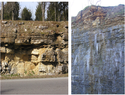
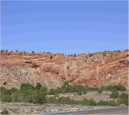

FIGURE 3.4 Massive sandstone in New Mexico showing relatively homogeneous rock. Photo courtesy of William J. Patterson.
EMPIRICAL EQUATIONS FOR PREDICTING PENETRATION CAPABILITY
Many equations predictive of earth-penetrating capabilities of EPWs have been developed over the past 40 years. In early 2000, two of the more widely used empirical equations were evaluated, and calculated depths were compared with large-scale tests of penetrators impacting into two different types of in situ rock formations at the Tonopah Test Range. Both of the equations predicted depths that agreed well with the Antelope Tuff and the Sidewinder Welded Tuff rock penetration data documented in the SNL Earth Penetration Database.3 One equation, developed by C.W. Young, was published in 1967.4 The most recent update was in 1997.5 The other equation was developed by M.J. Forrestal and published in 1994.6
Presented here (Box 3.2), Young’s equation illustrates the use of EP parameters to calculate maximum depths of penetration achievable in soil, low-strength rock, and medium-strength rock, as shown in Table 3.1.
The following sample calculation with Young’s equation uses the SEPW parameters and an impact velocity of 1,220 meters per second in low-strength rock.
|
BOX 3.2 Where D = depth of penetration in meters, α = 0.0000175, Ks = scaling factor, S = empirical target constant, N = penetrator nose coefficient, m = penetrator mass in kilograms, A = penetrator cross-sectional area in square meters, and Vs = impact velocity in meters per second. For soil the scaling factor Ks is defined as and For rock and concrete the scaling factor Ks is defined as and The nose coefficient N for a tangent ogive is defined as while the nose coefficient for a conical nose is defined by In the nose coefficient equations, Ln is the length of the penetrator nose in meters, and d is the diameter of the penetrator body in meters. The constant S is an empirical value, which depends on the target material. Its value is determined by measuring the depth of penetration for a given penetrator tested in a given geologic material and applying the equation to compute the value of S. A reasonable value of the empirical constant for a given geologic material is obtained by averaging several of the values for S obtained from several penetration tests. Once S has been determined experimentally for a given target material, the other variables in the equation may be altered to estimate depth of penetration into the same target material. |
TABLE 3.1 Empirically Estimated Maximum Credible Depths of Penetration of Earth-Penetrator Weapons in Three Types of Rock and Soil Media
Given
where α = 0.0000175, S = 1.3, nose CRH = 3, m = 411 kg, d = .274 m, and V = 1,220 m/s, then Ln/d = (CRH − .25)1/2 = (3 − .25)1/2 = 1.66, N = (.18 × 1.66) + .56 = .85, A = π(.274)2/4 = .059 m2, and (m/A)0.7 = (411/.059)0.7 = 492.
Hence
Based on data for deceleration versus time from a large number of tests, the best estimate of peak rigid body deceleration is 1.5 times the average deceleration:
MAXIMUM CREDIBLE DEPTHS OF PENETRATION
Table 3.1 presents empirically estimated maximum depths of penetration in three typical geologic materials. These depths were calculated using Young’s empirical equation. In order to add credibility to these estimates, the following data were used in the calculations: the physical properties of the W86 P II EPW and SEPW designs, penetrability numbers for the geologic media supported by test data, and impact velocities no greater than the highest velocities documented in the SNL Earth Penetration Database. The results of an EPW bomb optimized with the highest m/A feasible, within a 2,700 kilogram weight limit, are also shown to illustrate the ability of a robust EPW to minimize axial deceleration.
The 10,000 g peak deceleration capability of the SEPW and W86 P II EPW was the limiting factor in medium-strength rock. The impact velocity used in the calculations in low- and medium-strength rock was limited by the 10,000 g peak deceleration capability of the SEPW and W86 P II EPW. Also, impact velocity was limited to 1,525 meters per second, since no test data exist above 1,525 meters per second. The heavy weight of the EPW bomb limits the delivery system to aircraft only; therefore, the impact velocity for the EPW bomb was based on a reasonable maximum velocity obtainable from a high-altitude airdrop.
The heavy, high-cross-sectional-density bomb impacting at 500 meters per second achieved the maximum calculated depth in medium-strength rock, and the peak axial deceleration did not exceed 2,500 g. The low-yield EPW impacting at 1,500 meters per second achieved the maximum depth in low-strength rock and silty clay soil. Peak axial decelerations were no greater than 9,000 g and 1,500 g, respectively.
It must be kept in mind that these calculations assume that the penetrated medium is homogeneous; thus, these are the minimum expected depths. The maximum depth in soil could vary by ±20 percent based on the accuracy of Young’s equation.7 This would give a maximum depth of penetration for the low-yield EPW of approximately 140 meters in soil. The depths in rock could show even greater variability due to the nonhomogeneity of rock formations. Depths up to 50 percent greater than pretest estimates have been observed. The maximum depth in low-strength rock could be approximately 30 meters, and approximately 12 meters in medium-strength rock. Designers and test engineers are usually most interested in estimates of minimum depth since minimum depth results in the highest expected axial EPW deceleration.
W61 SYSTEM
The W61 EPW was intended to be an interim weapon to provide an EPW capability until the SEPW was fielded. The B61-7 was selected for conversion into an EPW because its internal components were required to survive relatively high axial and lateral acceleration loads. The B61-7 had to survive loading from an impact velocity of approximately 30.5 meters per second onto hard surfaces—impact conditions resulting from low-level, high-speed aircraft release and parachute-retarded lay-down. Detonation time was set for a safe aircraft separation time.
W61 predevelopment engineering began in 1987. Engineering development began in 1990, and the program was terminated in 1992. The W61 was designed to be a rapidly deployable system. The delivery system had the capability of delivering the W61 to the target surface at optimum impact conditions. For the targets of interest, optimum conditions were impact angles within 10 degrees of target normal, an angle of attack (angle between velocity vector and EPW centerline) of less than 2 degrees, and impact velocities around 245 meters per second.
Following are the initial basic guidelines from the DOD for the conversion of the B61-7 bomb into a W61 EPW:8
-
Minimize new component development,
-
Maximize the use of existing hardware, and
-
Minimize changes to the B61-7 electrical system.
A one-piece, cone-nosed penetrator case was designed to house the nuclear system and the warhead electrical system. The case was fabricated from high-strength steel with high fracture toughness. Since changes to components of the nuclear system and warhead electrical system were not allowed, the W61 EPW survivability limit was governed by the deceleration capability of the internal components. The system survivability level was determined by testing. Tests conducted during engineering development demonstrated that the W61 had the capability to survive penetration of 0.3 meter of concrete, hard soil, and low-strength rock at specified impact conditions. The W61 had an airburst and a contact-burst capability as well as subsurface-burst capability.
B61-11 EARTH-PENETRATING BOMB
The B61-11 was developed to replace the B53 gravity bomb, which had entered the stockpile in 1962. In 1988 an interim nuclear safety modification was made, resulting in the B53-1. However, even with the modification, the B53 did not completely meet standards for modern weapons safety, security, and reliability. Figure 3.5 and Table 3.2 show the final design and delineate the properties of the B61-11.
Following are the initial basic guidelines from the DOD for conversion of the B61-7 into an earth-penetrating bomb and the resulting actions:
-
Carry out a rapid development program.
-
The program was authorized on September 15, 1995.
-
Major assembly release occurred on December 30, 1996.
-
-
Minimize new component development.
-
EP case forgings from the cancelled W61 program were used.
-
No changes were made to the B61-7 nuclear system.
-
No changes were made to the B61-7 electrical system.
-
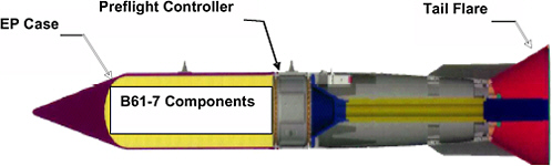
FIGURE 3.5 Final design of the nuclear, earth-penetrator (EP) B61-11. SOURCE: Sandia National Laboratories. 2003. B61-11 Final Weapon Development Report (U), SAND 2003-2344, Albuquerque, N.Mex. (Classified).
TABLE 3.2 Comparison of B61-7 and B61-11 Properties
|
Property |
B61-7 |
B61-11 |
|
Mass |
346 ± 7 kg |
549 ± 7 kg |
|
Nose, aluminum center case, and earth-penetrator case |
243 kg |
377 kg |
|
Preflight controller |
22.5 kg |
22.5 kg |
|
Tail |
80.7 kg |
150 kg |
|
Diameter |
0.33 m |
0.34 m |
|
Length |
3.6 m |
3.7 m |
Because changes to the nuclear system and warhead electrical system were not allowed, the survivable deceleration level of the B61-11 was limited to the deceleration limits of the B61-7 internal components. Penetration tests with functional warhead electrical-system components and simulated nuclear assemblies were conducted at different impact velocities into hard soil and frozen soil to demonstrate B61-11 capability in the targets of interest.
The classified military requirements for the B61-11 include limits for soil penetration capabilities, yield, center of gravity, reliability, stockpile quantities, and ballistic characteristics.
The B61-11 was developed to ensure a capability to continue to hold selected deeply buried targets at risk.
CURRENT ROBUST NUCLEAR EARTH PENETRATOR PROGRAM
The Robust Nuclear Earth Penetrator program is an engineering feasibility study. It was initiated in May 2003 with the intention of its being a 2-year study, with two teams working on the study: a Los Alamos National Laboratory (LANL) and Sandia National Laboratories Albuquerque (SNLA) team, and a Lawrence Livermore National Laboratory (LLNL) and Sandia National Laboratories Livermore (SNLL) team. The purpose of the program is to determine if, using the major components of an existing weapon system, an earth-penetrator system can be designed that can hold at risk a significantly larger number of targets than the B61-11 can. The LANL/SNLA team’s focus is the B61-7, and the LLNL/ SNLL team is addressing the B83. The basic approach is to increase the cross-sectional density of the
EPW when possible and to increase the deceleration capability level of the internal components. No changes in the parent weapon yield are allowed. The study is allowed to address potential changes to internal components, as long as the changes do not require any nuclear certification tests. Owing to budget constraints the study is now limited to the robust nuclear earth penetrator (RNEP) being studied by the LLNL/SNLL team. At this time there is no decision on when or if the LANL/SNLA team will restart its study.
Following are general guidelines from the DOD for the RNEP under study by the LLNL/SNLL team:9
-
The RNEP weapon is required to be able to do the following:
-
Survive penetration and not rebound from the target;
-
Reach a certain depth in a specified geology (the “threshold”);
-
Preserve or improve original weapon functionality; and
-
Preserve or improve original weapon safety, security, and reliability.
-
-
Regarding the compatibility of the RNEP with delivery aircraft:
-
The maximum weight, length, and diameter of the EPW case are to be determined by delivery aircraft requirements.
-
-
Modifications to the Arming, Fusing, and Firing (AF&F) system are allowed.
-
The AF&F capability level is to be determined by structural testing.
-
-
Modification of the nuclear system is allowed provided no nuclear certification testing is required.
The properties of the LLNL/SNLL RNEP are as follows:
-
Mass, including tail kit—1,379 kg,
-
Diameter—0.53 m, and
-
Penetrator length (may be extended by tail kit)—2.54 m.
Following are guidelines from the DOD regarding the RNEP guidance system:
-
RNEP is to be a guided and controlled weapon system. Its guidance system will do the following:
-
Allow for precise targeting,
-
Allow for optimization of angle of attack and incidence control, and
-
Minimize the stresses on the EPW system.
-
-
RNEP system capability will be determined by experimentation, test, and analysis.
-
The RNEP survivability level is set by the structural limit of the nuclear system and the arming, fusing, and firing system.
-


