


Below is the uncorrected machine-read text of this chapter, intended to provide our own search engines and external engines with highly rich, chapter-representative searchable text of each book. Because it is UNCORRECTED material, please consider the following text as a useful but insufficient proxy for the authoritative book pages.
316 7.1 introduction This chapter introduces basic principles related to fatigue and fracture in steel bridges and discusses factors that cause fatigue and fracture. Various available options for re- pairing observed cracking in steel bridges are also presented. These options are adapted from the Manual for Repair and Retrofit of Fatigue Cracks in Steel Bridges (Dexter and Ocel 2013) and are proposed as a guide for the detailing of repairs and retrofits for fatigue cracks. This chapter only contains summarized information from this manual and thus should not be the only means used to develop specifications needed for the repair and retrofit of fatigue-damaged details. Refer to the referenced manual (Dexter and Ocel 2013) for additional detailed descriptions of the topics, procedures, and ex- amples presented in this chapter. Further, this chapter should be used in combination with other existing codes, specifications, and engineering judgment. 7.2 bAckground Cracks found in steel elements of bridges can usually be attributed to fatigue. Fatigue in metals is described as the process by which cracks initiate and grow under repeated loads. These fatigue cracks can lead to failure if the remaining uncracked section can no longer carry the loads experienced by the structure. In the case of bridge struc- tures, fatigue failure usually occurs as a result of the crack growth that initiates from existing discontinuities. In fatigue, these existing discontinuities are treated as existing cracks. All fabricated steel elements contain discontinuities, and most contain high stress concentrations at weld toes. The stress levels causing the failure due to fatigue are usually considerably lower than those that can cause failure under static loading 7 FATiGUE AND FRACTURE OF STEEL STRUCTURES
317 Chapter 7. FATiGUE AND FRACTURE OF STEEL STRUCTURES conditions. Fatigue cracks usually form under large numbers of load cycles and worsen with higher stress ranges (Fisher et al. 1998). Cracks and discontinuities are expected in steel structures and do not necessarily mean that the member will fail as long as the proper precautions are taken. Most modern structures are redundant and allow for the excess stresses in the cracked mem- bers to be redistributed, thus keeping the fatigue crack from propagating any further without intervention. However, it is important to assess tension elements that contain cracks to determine the potential for fracture. Bridges that do not possess redundancy for the redistribution of stresses face failure of the entire structure if one of the mem- bers were to fail; these members are known as fracture critical members. These struc- tures call for more careful attention, as a fatigue crack can be detrimental to the life of the bridge (Fisher et al. 1998). Fatigue failure often occurs very suddenly, with little warning; however, the pro- cess begins at the onset of the structureâs usage, implying that fatigue is progressive. Another important aspect of fatigue is that it is a local phenomenon, occurring in areas of high stresses and strains due to load transfer, abrupt changes in geometry, residual stresses, and material imperfections. The damage caused by fatigue is permanent and is not reversible. Fatigue cracks exist in many structures, but not all of them are criti- cal; certain criteria must be met before the cracks are detrimental to the structural element. Fracture (i.e., separation of a component into two or more parts) occurs once the remaining uncracked portion of the member can no longer handle the stresses and strains (Stephens et al. 2001). The entire fatigue process includes the nucleation (formation) of a fatigue crack, crack propagation (growth), and final fracture (failure). The nucleation of a fatigue crack takes place at the microscopic level, dealing primarily with the microstructure of the material. Discontinuities are common sites of crack nucleation and include per- sistent slip bands, inclusions, pores, second-phase particles, corrosion pits, voids, and twin and grain boundaries. However, cracks primarily tend to nucleate along slip lines in the direction of planes of maximum shear (Stephens et al. 2001). Once a fatigue crack forms and continues to undergo repeated loading, it tends to coalesce and grow along the plane of maximum tensile stress range. The crack will grow with each load cycle, even if only by a small amount. As the cracked member is loaded, the crack will open, causing an increase in stress at the crack tip; this increased stress consequently drives the crack to grow even larger. Fatigue crack growth is bro- ken up into two stages, Stage 1 and Stage 2, as seen in Figure 7.1. Stage 1 refers to the growth in the direction of the principal shear plane, and Stage 2 refers to the growth along the plane of maximum principal tensile stress. Fatigue cracks tend to grow trans- crystalline (through grains), but some fatigue cracks can grow intercrystalline (along grain boundaries). Crack growth mechanisms include striation formation, microvoid coalescence, and microcleavage. Striations are microscopic âripplesâ that are repre- sentative of the fatigue cycles experienced by the element. Striations can be used to investigate the rate of crack growth and are very useful in forensic studies. Microvoid coalescence involves the formation, growth, and joining of microvoids during plastic
318 DESiGN GUiDE FOR BRiDGES FOR SERviCE LiFE deformation. Microcleavage is a fracture along specific crystallographic planes and tends to be a brittle fatigue mode (Stephens et al. 2001). This section presents only a brief and very general summary of the fatigue pro- cess, but it is important for the practicing engineer to understand the principles of the fatigue damage process in order to be proficient in fatigue design. Minimizing fatigue cracks can be achieved by first avoiding the use of known details that have proven to have low resistance to fatigue. Fatigue cracks can also be reduced by the use of better fabrication and welding processes that decrease the num- ber of inherent defects and also allocate for the detection and repair of such cracks before the bridge is opened to the public. In-service inspection is necessary to discover new fatigue cracks and monitor existing ones. Once cracks are located through the inspection process, it is necessary to perform an assessment to determine the risk of fracture. Furthermore, for the proper repair methods to be implemented, the cause and type of crack need to be determined (Fisher et al. 1998). Methods for determining the fatigue resistance of a detail include nominal stress approach, hot-spot stress approach, and fracture mechanics approach. 7.2.1 nominal Stress Approach The nominal stress design approach is a simple way to determine the fatigue resistance of a detail by using equations for bending and axial loads to compute the nominal stress near a weld toe. Test data from full-scale fatigue tests are needed in order to use this design method. Stress ranges (S) versus the number of cycles to failure (N) curves are developed from the test data. The curves are grouped into categories to aid in organizing the details according to their fatigue resistance. Figure 7.2 shows the S-N curves as used in AASHTO specifications. The detail categories reflect and account for Figure 7.1. Schematic of Stages 1 and 2 of fatigue crack growth. Source: Stephens et al. 2001.
319 Chapter 7. FATiGUE AND FRACTURE OF STEEL STRUCTURES Source: AASHTO (2012). Figure 7.2. S-N curves used in AASHTO, American Institute of Steel Construction (AISC), American Welding Society (AWS), and American Railway Engineering and Maintenance-of-Way Association (AREMA) specifications. the variations in the combined geometric and local notch stress concentrations. Each category has a constant-amplitude fatigue limit (CAFL), also referred to as constant- amplitude fatigue threshold (CAFT). Stress ranges that fall below the CAFL are not expected to exhibit any fatigue failures during constant-amplitude testing. Most bridges with a service life of 75 years are designed as having an infinite life, with no occurrence of fatigue cracking. In the LRFD Bridge Design Specifications (LRFD specifications) (AASHTO 2012), the fatigue design live load is taken as 0.75 times the HS20 for finite load-induced fatigue life and 1.5 times the HS20 for infi- nite load-induced fatigue life. This fatigue load is used to calculate the nominal stress ranges to be used with the S-N curves. If the resulting nominal stress range is less than half of the CAFL, it is assumed the bridge is designed for infinite life. This ensures that the fatigue limitâstate stress range is below the CAFL. The fatigue limit state is the stress range in which 0.01% of the test data exceeds the CAFL (AASHTO 2012). Figure 7.2. S-N curves used in AASHTO, American Institute of Steel Construction (AISC), American Welding Society (AWS), and American Railway Engineering and Maintenance-of-Way Association (AREMA) specifications. Source: AASHTO 2012.
320 DESiGN GUiDE FOR BRiDGES FOR SERviCE LiFE 7.2.2 Hot-Spot Stress Approach The hot-spot stress approach is similar to the nominal stress approach, except that the S-N curves are based on the geometric stress ranges, also known as hot-spot stresses. This process is beneficial in instances when the nominal stress approach breaks down, such as offshore tubular structures in which the fatigue resistance is heavily dependent on the geometry of the tubes. Using this design process involves determining the stress concentration factor by using parametric equations or finite element analysis. Dis- advantages arise with the variability of different hot-spot definitions, varying baseline S-N curves, and difficulties with the CAFL. 7.2.3 fracture mechanics Approach In the case of bridge structures, the fracture mechanics approach is the most complex approach and tends to be difficult to implement during the bridge design process. The fracture mechanics approach is divided into two main categories: linear elastic fracture mechanics (LEFM) and plastic fracture mechanics. LEFM is used when remotely ap- plied stresses are in elastic ranges. It should be noted that at the crack tip, a stress sin- gularity is always present and stresses tend to approach infinity. In the case of LEFM, the rate of crack growth is related to stress ranges, but in the case of plastic fracture mechanics, rate of crack growth needs to be related to a parameter related to energy dissipation or plastic strain (Azizinamini and Radziminski 1989). For the case of LEFM, the Paris law, shown in Equation 7.1, can be useful in deter- mining the crack growth rate for many engineering applications: da dN C Km= â â (7.1) where a = crack size (mm or in.), N = number of cycles, C = material constant, DK = stress intensity factor range MPa m or ksi in. 1 2 1 2â â ï£ï£¬   , and m = material constant. Although fracture mechanics is rarely used in design, it can serve as a qualitative tool to give the designer a better understanding of structures containing cracks and discontinuities. Fracture mechanics is best suited when the local behavior of structure in the vicinity of the crack is of interest, such as how fast the crack will grow. However, addressing such problems requires a detailed understanding of the parameters that affect crack performance.
321 Chapter 7. FATiGUE AND FRACTURE OF STEEL STRUCTURES 7.3 crAck detection techniQueS Cracks are not always obvious to the human eye and can be difficult to locate at times. Several methods in practice aid in the detection of cracks, two of which are dye pen- etrant and magnetic particle inspection. Dye penetrant consists of three parts: cleaning the area of a suspected crack, appli- cation of a liquid dye, and finally the application of a white developer. Figure 7.3 shows a crack exposed using a red dye penetrant. Magnetic particle inspection works by inducing a magnetic field by using a hand- held device around a crack. The magnetic field is disrupted at the crack, and a con- centration of a magnetic field results. A fine iron powder is sprinkled over the area of interest and is attracted to the magnetic field, exposing the crack. 7.4 rePAir And retroFit methodS This section presents several methods for the repair and retrofit of fatigue critical details. Such techniques can be categorized as surface treatments, repair of through- thickness cracks, and connection or global structure modification to reduce the causes of cracking. 7.4.1 Surface treatments Surface treatments are usually performed on weld toes to increase the fatigue strength of uncracked welds. Such treatments, including grinding, gas tungsten arc, and impact treatments, aim to improve the weld geometry in order to reduce stress concentrations, remove discontinuities, or reduce residual tensile stresses. Crack Figure 7.3. Crack exposed using a red dye penetrant.
322 DESiGN GUiDE FOR BRiDGES FOR SERviCE LiFE 7.4.2 Reshaping by grinding Grinding can be used as an effective measure for increasing the fatigue life of the weld toe by removing portions of the weld that contain small cracks. Grinding has proven more effective on larger welds in structures such as offshore structures with large tubular joints. It should be noted that grinding is ineffective against microcracks because the process tends to create new microcracks as it removes the existing ones. Two types of grinding methods are commonly used: disc grinding (Figure 7.4) and burr grinding (Figure 7.5). Both methods have advantages and disadvantages. Disc grinding can be more effective at removing the weld material with faster speeds; however, the operator needs to use caution to avoid gouging the metal or removing too much of the weld material. Burr grinding is typically easier to operate and works in more confined spaces than disc grinding (Gregory et al. 1989). 7.4.3 gas tungsten Arc or Plasma Remelting Gas tungsten arc aims to reduce the stress concentrations at the weld toe and also remove slag intrusions. This process involves melting a small volume of the weld toe and base material by using tungsten electrodes. For this process to effectively increase the weldâs fatigue life, the operator needs great skill, which consequently increases the cost of this process. Figure 7.4. Disc grinding.
323 Chapter 7. FATiGUE AND FRACTURE OF STEEL STRUCTURES 7.4.4 impact treatments Compressive residual stresses can be induced around the weld toe by using impact treatments. These compressive stresses reduce the effective tensile stress range, extend- ing the fatigue life of welds. Since impact treatments enhance the weld profile and residual stresses, the process can only affect stresses transverse to the impacted weld. Thus, impact treatments are most effective on transversely loaded welds and have no effect on longitudinally loaded welds. The most common types of impact treatments include air hammer peening and ultrasonic impact treatment. Air hammer peening uses an air-powered hammer with a blunt tip that plastically deforms the weld toe. This simple method can increase the fatigue resistance by at least one detail category. For instance, a Category C detail could be improved to a Category B detail. Air hammer peening reduces the number of slag intrusions, but at the same time it creates lap-type defects. These lap-type defects can be reduced by light grinding following the peening (Hausammann et al. 1983). Ultrasonic impact treatment (UIT), which uses low-amplitude and high-frequency displacements, has proven to be more effective than hammer peening. However, this treatment can be more costly as it is still a proprietary method (Tryfyakov et al. 1993; Roy et al. 2003). Figure 7.5. Burr grinding.
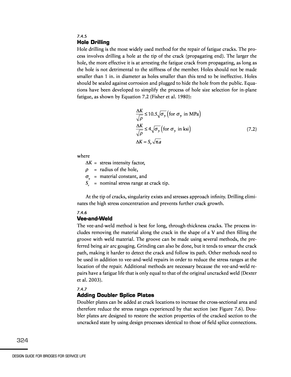
324 DESiGN GUiDE FOR BRiDGES FOR SERviCE LiFE 7.4.5 Hole Drilling Hole drilling is the most widely used method for the repair of fatigue cracks. The pro- cess involves drilling a hole at the tip of the crack (propagating end). The larger the hole, the more effective it is at arresting the fatigue crack from propagating, as long as the hole is not detrimental to the stiffness of the member. Holes should not be made smaller than 1 in. in diameter as holes smaller than this tend to be ineffective. Holes should be sealed against corrosion and plugged to hide the hole from the public. Equa- tions have been developed to simplify the process of hole size selection for in-plane fatigue, as shown by Equation 7.2 (Fisher et al. 1980): K K K S a 10.5 for in MPa 4 for in ksi y y y y r Ï Ï Ï Ï Ï Ï ( ) ( ) â ⤠â ⤠â = Ï (7.2) where DK = stress intensity factor, r = radius of the hole, sy = material constant, and Sr = nominal stress range at crack tip. At the tip of cracks, singularity exists and stresses approach infinity. Drilling elimi- nates the high stress concentration and prevents further crack growth. 7.4.6 Vee-and-Weld The vee-and-weld method is best for long, through-thickness cracks. The process in- cludes removing the material along the crack in the shape of a V and then filling the groove with weld material. The groove can be made using several methods, the pre- ferred being air arc gouging. Grinding can also be done, but it tends to smear the crack path, making it harder to detect the crack and follow its path. Other methods need to be used in addition to vee-and-weld repairs in order to reduce the stress ranges at the location of the repair. Additional methods are necessary because the vee-and-weld re- pairs have a fatigue life that is only equal to that of the original uncracked weld (Dexter et al. 2003). 7.4.7 Adding Doubler Splice Plates Doubler plates can be added at crack locations to increase the cross-sectional area and therefore reduce the stress ranges experienced by that section (see Figure 7.6). Dou- bler plates are designed to restore the section properties of the cracked section to the uncracked state by using design processes identical to those of field splice connections.
325 Chapter 7. FATiGUE AND FRACTURE OF STEEL STRUCTURES 7.4.8 Posttensioning Posttensioning methods that are applied to cracked sections can prolong the fatigue life of the structure. Posttensioning induces forces on the cracked section that put the effective stress ranges into compression, keeping the crack closed and unable to propa- gate. Drilling a hole at the crack tip is recommended in addition to using one of the various types of posttensioning methods. 7.4.9 Detail modification Detail modification is used when it is necessary to lower the effective stress range in order to repair the cracked section. This modification can be achieved in a number of ways, among them increasing the cross-sectional area, changing connection geometry, or eliminating sharp corners from details. 7.5 FAtigue cAuSed by SecondAry StreSSeS Secondary stresses can arise when a structure is designed as a series of individual components and the designer does not account for the global system behavior. These stresses can cause unexpected fatigue cracking. This section discusses these stresses and the methods used to repair the fatigue cracks that form under secondary stresses. 7.5.1 out-of-Plane Distortion Differential displacements between girders and lateral bracing elements introduce fatigue to the web-gap regions of the girders. This phenomenon causes highly local- ized bending of the web gap, as shown in Figure 7.7, causing fatigue cracks. In order Figure 7.6. Bolted doubler plate repair.
326 DESiGN GUiDE FOR BRiDGES FOR SERviCE LiFE to properly repair the fatigue cracks the out-of-plane bending needs to be reduced or eliminated. It is important to note that web-gap fatigue retrofits need to maintain symmetry. 7.5.1.1 Repair Methods Specific to Out-of-Plane Distortion 7.5.1.1.1 Hole Drilling Hole drilling can be effective at reducing the crack growth but not eliminating the cause of the fatigue. See Section 7.4.5 on hole drilling for additional details; however, note that the hole-sizing equations were developed for in-plane fatigue and may not have the same effect on out-of-plane distortionâinduced fatigue. 7.5.1.1.2 Diaphragm or Crossframe Removal Diaphragms and crossframes transfer the secondary forces between girders when dif- ferential displacement of the girders occurs. Removing these members eliminates the causes of the fatigue-induced cracks in the web gaps. However, several issues of con- cern have arisen from the removal of such bridge elements. It has been shown that the removal of the lateral bracing elements can be detrimental to the structure when they are not properly removed. In negative moment regions, the lateral bracing keeps the compression flange from buckling. Also, if the diaphragms and crossframes are removed because the bridge deck needs to be replaced, no lateral bracing will exist to keep the girders stable when the deck is removed. Some studies show that crossframes Figure 7.7. Web-gap fatigue mechanism from displacement continuity: (top) differential girder displacements cause a force couple to develop within the diaphragm and (bottom) zoomed view of web-gap deformation girder displacement.
327 Chapter 7. FATiGUE AND FRACTURE OF STEEL STRUCTURES are effective to some extent in distributing the applied traffic loads (Brakke 2002; Flemming 2002). However, extensive investigation of crossframes indicated that it is the stiffness of the deck that is mainly responsible for distribution of truck loads be- tween girders and that crossframes do not contribute to load distribution (Azizinamini et al. 1995a, 1995b). 7.5.1.1.3 Diaphragm Repositioning It has been shown that lowering diaphragms closer to the bottom flange of the girders (in negative moment regions) and reducing the number of connecting bolts can reduce the effective stress range. This was seen in a case study of the I-35W Bridge over the Mississippi River in Minneapolis, Minnesota (Bergson 1998). See Figure 7.8. 7.5.1.1.4 Bolt Loosening Loosening the connection bolts can reduce the effect of the out-of-plane displace- ments. The holes are specified to be larger than the size of the bolts, and this extra space negates the effects of small differential displacements. However, the effectiveness of loosening the bolts is limited to the extra space provided by the oversized holes and whether the holes are in bearing due to misaligned connection plates. Additional mea- sures are needed to ensure that the loosened nut does not fall off the bolt as a result of structural vibrations (Wipf et al. 1998). 7.5.1.1.5 Web-Gap Stiffening Permanently attaching the connection plate to the girder flange can reduce or eliminate the effects of out-of-plane displacements. Several methods exist for the attachment of the connection plate to the girder flange: all welded, all bolted, welded and bolted, adhesives, and nails. Figure 7.8. Schematic of diaphragm repositioning retrofit specified on Minnesota Bridge. Figure 7.8. Schematic of diaphragm repositioning retrofit specified on Minnesota Bridge.
328 DESiGN GUiDE FOR BRiDGES FOR SERviCE LiFE 7.5.1.1.5a Welded Attachments The all-welded retrofit for connection plates can be difficult to implement. For in- stance, the welded connection itself can cause fatigue cracks (Keating et al. 1996). In addition, it can be very difficult to properly weld high-strength steels as well as flanges that are embedded in concrete. Although AASHTO now requires transverse welds or bolted connections on both the girder flanges for the positive attachment of the con- nection plate, the all-welded attachment retrofit has rarely been specified for reasons previously mentioned (AASHTO 2012). Figure 7.9 shows a fillet welded connection plate-to-girder detail. 7.5.1.1.5b Bolted Connections The connection plate can be bolted to the girder flange by using angles or sections. It is important to properly size the angles and tee sections and determine the number of bolts needed in order to provide for the proper stiffness of the section. Bolted tee sec- tions are preferred over double angles because they provide greater stiffness (Fisher et al. 1990). See Figure 7.10. 7.5.1.1.5c Welded and Bolted Connections Hybrid connections that use both welded and bolted connections may be more benefi- cial in areas with certain clearance issues. Figure 7.9. Connection plate-to-girder fillet weld detailing. Source: Keating 2001.
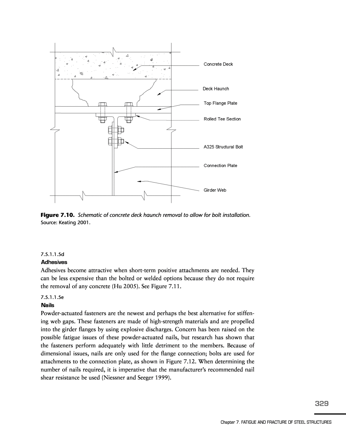
329 Chapter 7. FATiGUE AND FRACTURE OF STEEL STRUCTURES 7.5.1.1.5d Adhesives Adhesives become attractive when short-term positive attachments are needed. They can be less expensive than the bolted or welded options because they do not require the removal of any concrete (Hu 2005). See Figure 7.11. 7.5.1.1.5e Nails Powder-actuated fasteners are the newest and perhaps the best alternative for stiffen- ing web gaps. These fasteners are made of high-strength materials and are propelled into the girder flanges by using explosive discharges. Concern has been raised on the possible fatigue issues of these powder-actuated nails, but research has shown that the fasteners perform adequately with little detriment to the members. Because of dimensional issues, nails are only used for the flange connection; bolts are used for attachments to the connection plate, as shown in Figure 7.12. When determining the number of nails required, it is imperative that the manufacturerâs recommended nail shear resistance be used (Niessner and Seeger 1999). Figure 7.10. Schematic of concrete deck haunch removal to allow for bolt installation. Source: Keating 2001.
330 DESiGN GUiDE FOR BRiDGES FOR SERviCE LiFE Leave a minimum 6.4 mm (0.25 inch) gap between angle/tee and longitudinal weld of girder to prevent a fretting fatigue problem Leave a minimum 6.4 mm (0.25 inch) gap between angle/tee and longitudinal weld of girder to prevent a fretting fatigue problem Figure 7.12. Work plan for web-gap retrofit using nails. Figure 7.11. Work plan for stiffening retrofit of web gaps with adhesives. Source: Hu 2005.
331 Chapter 7. FATiGUE AND FRACTURE OF STEEL STRUCTURES 7.5.1.1.6 Web-Gap Softening Web-gap softening entails the removal of portions of material to make the web gap more flexible. See Figure 7.13. A portion of the connection plate can be removed to increase the size of the web gap and therefore reduce the stresses resulting from out-of-plane distortion. After flame cutting the connection plate, it is important to grind the portion of the web smooth and flush where the connection plate was previously attached. A simpler and faster approach to softening the web gap would be drilling large holes in the web of the girder close to the web gap, as shown in Figure 7.14. This process is much like the smaller-hole retrofits discussed earlier; however, the larger- diameter holes are able to capture several cracks as opposed to the âSwiss cheeseâ method of numerous smaller holes. Figure 7.13. Work plan for web-gap softening used on Poplar Street Bridges in East Saint Louis, Illinois. Source: Koob et al. 1985.
332 DESiGN GUiDE FOR BRiDGES FOR SERviCE LiFE 7.5.2 tie girderâfloor Beam Connection Tied arch bridges exhibit a specific type of web-gap fatigue in the connections between the floor beams and the tie girders. This fatigue arises from the displacement incom- patibility between the floor beams that are composite with the bridge deck and the noncomposite tie girder. The mode of deformation is illustrated in Figure 7.15. Several retrofits have been implemented in the field and subsequently studied. These studies are presented in the report (Dexter and Ocel 2013) from which this section has been adapted. 7.5.3 Cantilever Bracket Cracking Floor beam cantilevered brackets are used on bridges with large deck overhangs and can be susceptible to secondary stress fatigue. Several retrofit options exist for reduc- ing the displacement incompatibility of the girder and floor beams. These retrofits deal mainly with the modification of the tie plates that span over the girders. The main idea is either to remove any positive attachments between the girders and tie plates or to add spacer plates to create a gap between the elements. Figures 7.16 through 7.18 show the deformation modes and possible retrofit options. Figure 7.14. Schematic of typical large-diameter hole retrofit. Source: Koob and McGormley 1998.
333 Chapter 7. FATiGUE AND FRACTURE OF STEEL STRUCTURES Figure 7.15. Schematic of tie girder-to-floor beam cracking driving force: (a) a generic deck system of an arch bridge using a tie girder, (b) close-up view of members showing deformation caused by tie girder rotation, and (c) close-up view of web-gap deformation of floor beam web.
334 DESiGN GUiDE FOR BRiDGES FOR SERviCE LiFE Figure 7.16. Typical cross section of a two-girder bridge with cantilever bracket outriggers. Figure 7.16. Typical cross section of a two-girder bridge with cantilever bracket outriggers. Figure 7.17. (left) Zoomed-in view of tie plate detail and (right) and deformation mode that causes cracking.
335 Chapter 7. FATiGUE AND FRACTURE OF STEEL STRUCTURES 7.6 retroFit vALidAtion oF SecondAry StreSS FAtigue Because of the unknown nature of retrofitting web-gap fatigue, it is necessary to vali- date particular retrofits before retrofitting an entire bridge. The simplest plan to vali- date a particular retrofit is to first instrument an uncracked detail and then perform the necessary retrofit and validate whether the retrofit adequately lowered the stress ranges and out-of-plane displacements. Typical instrumentation includes the use of strain gauges or displacement measurement devices, or both. Strain gauges are common and effective instruments used to determine the effec- tive stress ranges of bridge elements. Strain gauges can be either spot welded or glued to the element of interest. Figure 7.19 shows preferable strain gauge layouts for retrofit validation. Measuring the displacements has become the preferable method for validating retrofits because displacement measurements are quicker and more cost-effective than strain measurements. That displacement gauges are only usable for stiffening retrofits should be taken into account. Two common types of displacement measuring devices are linear variable differential transformers (LVDTs) and dial gauges. Figure 7.20 shows a schematic for the placement of the devices to measure the web-gap displace- ment. Maximum distortion-induced fatigue strains and stresses do not always cor- relate with the largest values of differential deflection, and an instrumentation plan based primarily on displacements may not capture the whole picture. In the final analysis, however, the choice of instrumentation to validate the retrofit type is context sensitive. The designer must select an instrumentation type that best matches the retrofit type. Figure 7.18. Retrofit of tie plate cracking through addition of spacer plates.
336 DESiGN GUiDE FOR BRiDGES FOR SERviCE LiFE 7.7 LoAd-controLLed FAtigue crAck rePAir 7.7.1 Coverplates Several methods have been explored in the retrofitting of coverplates, including grind- ing, air hammer peening, gas tungsten arc, and bolted splice plates. Grinding has proven ineffective and is not recommended. Bolted splice plates are an effective option for girders with severed flanges and in instances in which the listed methods are unde- sirable. Figure 7.21 shows a splice plate retrofit. Figure 7.19. Recommended strain gauge placement for retrofit validation for (top) floor beamâtie girder connection or beam cope cracking and (bottom) out-of-plane distortion.
337 Chapter 7. FATiGUE AND FRACTURE OF STEEL STRUCTURES 7.7.2 Eyebars and Hangers Eyebars are long slender bars or rods with forged eyes at the ends that are commonly used as tension members in truss bridges. Hangers are vertically oriented tension mem- bers that support load. Because eyebars and hangers are often the sole components supporting the particular tensile load, they are usually classified as fracture critical members; inherent flaws can lead to fatigue cracks. Figure 7.20. Recommended web-gap displacement instrumentation. Figure 7.21. Detailing of splice plate retrofit for cracked coverplate details.
338 DESiGN GUiDE FOR BRiDGES FOR SERviCE LiFE Assessing the integrity of eyebars, especially in old truss bridges, is very difficult. An example of an eyebar with extensive corrosion is shown in Figure 7.22. In the case of truss bridges, adding truss members, rather than replacing them, is recommended. Removing even a single truss member or connection could easily lead to bridge failure. In retrofitting many existing old truss bridges, extensive corrosion of eyebars in tension could be addressed by adding additional tension members while keeping the existing ones in place. Figure 7.23 shows a possible retrofit alternative for eyebars in tension in existing truss bridges (Azizinamini 2002). Figure 7.22. Corrosion of eyebar connection. Figure 7.23. Retrofit option for eyebar connection.
339 Chapter 7. FATiGUE AND FRACTURE OF STEEL STRUCTURES 7.7.3 temporary tack Welds Tack welds used to temporarily hold members in place during construction can be sources of concern for creating fatigue cracks. Fatigue cracks tend to form at the ends of the tack welds and then propagate into the base metal. The most susceptible types of tack welds are longitudinal and those located at the end of tack-welded members. Tack welds can be removed using grinding methods. 7.7.4 Connection Angles Connection angles used to connect diaphragms to girder webs are susceptible to fatigue cracking as a result of differential girder displacements, as shown in Figure 7.24. The thickness of such angles needs to be reduced in order to reduce the flexural rigidity of the elements and negate the causes of the differential girder displacements. Equa- tion 7.3 helps determine the proper angle thickness to prevent cracking (Dexter and Fisher 1999): Figure 7.24. Deformation mode of connection angles as a result of displacement compatibility.
340 DESiGN GUiDE FOR BRiDGES FOR SERviCE LiFE t g L 12 2 ⤠ ï£ï£¬   (7.3) where t = angle thickness, g = bolt gauge, and L = distance between girders. 7.7.5 Web gusset Plates Another source of fatigue cracks are web gusset plates, which can experience fatigue damage in response to weld root defects and locations of intersecting welds. Intersect- ing welds can be retrofitted by coring holes at the intersections; this procedure will not only remove the intersecting welds, but also reduce the web constraint. See Fig- ures 7.25 and 7.26. Figure 7.25. (top) Typical cross section of a deep girder bridge and (bottom) plan view of web gusset detail.
341 Chapter 7. FATiGUE AND FRACTURE OF STEEL STRUCTURES Fatigue cracks have also been found to initiate from the ends of the gusset plates and propagate into the girder webs. This issue can be solved using impact treatments or grinding the weld termination, as shown in Figure 7.27. Figure 7.26. Retrofit detail for gusset plates with intersecting welds (Crack Site #1). Figure 7.27. Detailing of Crack Site #2 retrofit. 1. Grind weld termination using a carbide burr grinder according to figure below. Make sure to transition the weld tangent to the girder web. 2. Inspect ground area near weld to make sure all weld discontinuities had been removed. 3. If evidence of discontinuities still exist, grind more weld away until clean weld is found. 4. Polish ground area with sanding wheel to ANSI roughness of 500 or less. 5. Prime and paint ground area as required.
342 DESiGN GUiDE FOR BRiDGES FOR SERviCE LiFE 7.7.6 Longitudinal Stiffeners Fatigue cracks can form at the butt welds of longitudinal stiffeners, primarily as a re- sult of poor workmanship and inherent defects of the welds. Drilling a large-diameter hole in the longitudinal stiffener located next to the girder has proven to keep the crack from developing into the girder web. See Figure 7.28. 7.7.7 Coped Beam Ends Fatigue cracks have also been observed in coped beam ends. These cracks can be at- tributed to stresses from flame-cut copes not ground smooth or the presence of bend- ing moments at these copes, which were designed as simply supported. Square-cut copes have the least fatigue resistance. Holes can be drilled as a retrofit option, or the cope can be cut back with a radius. Figure 7.28. Work plan of longitudinal butt weld retrofit.
