


Below is the uncorrected machine-read text of this chapter, intended to provide our own search engines and external engines with highly rich, chapter-representative searchable text of each book. Because it is UNCORRECTED material, please consider the following text as a useful but insufficient proxy for the authoritative book pages.
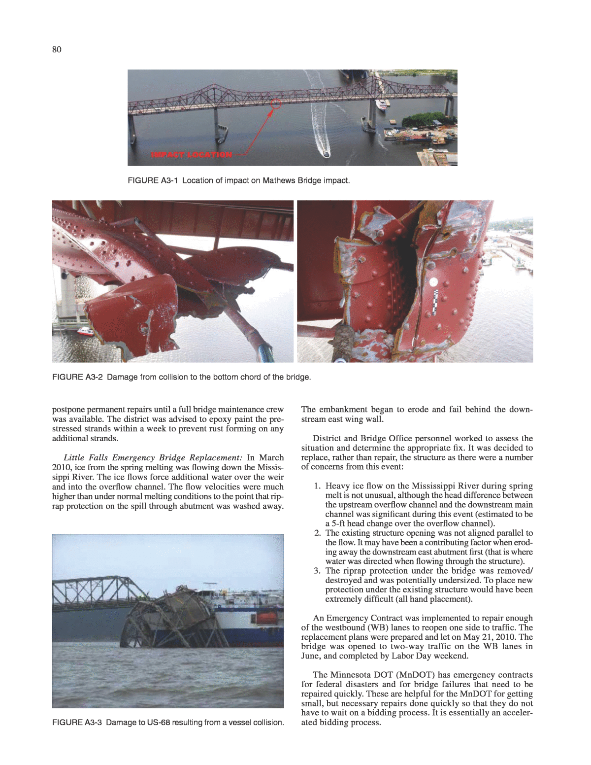
79 As part of the surveys, the state engineers have shared their experi- ences from extreme events that resulted in emergency response actions. These experiences together with the information on emer- gency response planning from chapter four will provide a solid implementation procedure for the developed emergency plans. Different subsections of this chapter discuss different events such as impact, earthquake, floods, hurricanes, and fire. Under each event category, the experiences of one or more states that provided their voluntary response is listed. 1. Impact Florida Department of transportation (FDOt) and truck Impact to truss members Mathews Bridge Impact: In this event, a noncommissioned United States Naval Ship (USNS) struck the north bottom truss chord of the Mathews Bridge while under tow and on its way to the North Florida Shipyard, located on the riverâs west bank, between the Mathews and Hart bridges (Figure A3-1). The shipâs stern ramp was in the upright position and the port-side ramp buttress did not clear the bridgeâs lower chord. Because all but the shipâs stern ramp had already passed beneath the bridge, the momentum was too great to overcome and the north lower chord of the bridge was damaged. The impact bent the shipâs buttress back far enough that it only caused minor damage to other below deck members of the bridge as the ship continued through to the other side. Figure A3-2 presents the extent of damage observed during this event. The immediate response was to close the bridge to traffic and prevent other boats from passing underneath. Concurrently FDOT confirmed the extent and severity of damage and sent a Declaration of Emergency (DoE) letter to Floridaâs secretary of transportation. With the DoE letter, FDOT was able to move forward without fol- lowing the normal advertising protocols in place for traditional con- tracts. FDOTâs first act was to assemble an emergency response team including bridge design engineers, contractors, surveyors, steel heat straightening professionals, steel fabricators, pin testers, bridge inspectors and CEIs, and strain gage professionals. Within 76 hours of impact, a bid package was prepared for potential con- tractors. The contract and scheduling included a 40 calendar day contract time with an incentive/disincentive of $50k/day. Strain gages were installed on the bridge to monitor both the re-distribution of forces during the jacking process and the material response of specific members during de-tensioning (restoration of the bridge), load testing, and after the bridge was opened to traffic. The gages were installed on the north truss at panel points surrounding the damaged lower chord. Gages were also installed on upper chord gusset plates where possible buckling was a concern as well as on stringers nearest to the missing chord. Companion gages were installed on the identical panel points on the south truss to allow a comparison of gage outputs. The pur- pose of the gages after repair of the bridge was to look for signs of yielding and/or large stress ranges that would signal a potential fatigue concern. In addition, from the day after the impact through to the open- ing of the bridge, surveying was a daily occurrence. During the first week, D2 Bridge Inspectors surveyed positions along the deck to watch for signs of continual creep. Additionally, survey data gathered by Arc Surveying and Mapping was monitored at top of the deck in four positions and floor beam bottom flanges. Load tests were performed at two stages during the project: after completion of temporary repairs and after completion of per- manent repairs. The tests were performed using two FDOT flat- bed trucks, weighing 48,000 pounds each (unloaded). To load test the bridge, concrete blocks, weighing 2,000 pounds each, were stacked on top of the truck beds and the trucks then were driven over the bridge while making three stops along the way. Kentucky transportation cabinet (KYtc) and Vessel collision US 68 bridge collision: On January 26, 2012, an 8,679 ton cargo ship struck a 322-ft-long span of the 43 span 3,348-ft-long Eggnerâs Ferry Bridge, severing a critical connection to rec- reational, business, and educational centers. The bridge carries US-68 over Kentucky Lake on the Tennessee River (Figure A3-3). The closure required a 42-mile detour that caused major traffic disruptions and delays since the bridge was being used, on aver- age, by 2,800 cars a day. The KYTC looked into the use of a ferry system, but determined that it was not feasible due to water levels and vehicle capacity as it would only be able to transport 40 vehicles per hour. In response to this impact, the bridge was immediately closed. A KYTC inspection team rappelled down several piers on the bridge to check the structural integrity of each pier and specifi- cally looked at the construction joint where new pier sections were added to raise the height of the bridge deck when Kentucky Lake was impounded in the mid-1940s. An accelerated bridge construction process was used by creating a 320-foot steel truss offsite that was brought in by a barge and then lifted into place by cranes (Figure A3-4). The bridge was reopened in 17 weeks. The bridge was completed and opened to the public on May 25, 2012. minnesota Department of transportation (mnDOt) and Over Height collision Bridge 27V60 Collision: On July 12, 2011, an oversized vehicle hit the underside of bridge 27V60. The collision caused the west- bound right lane to be temporarily closed. The south fascia beam was impacted first and had the worst damage (Figure A3-5). The fascia beam had spalling around 2 in. deep over an area of about 10 ft2. Each pre-stressed strand consisted of seven wires. The outer bottom two strands had wires that were damaged such that the entire strand should be disregarded in the structural analysis. The third interior beam had some spalling, but no strands were exposed. None of the beams had any indication of cracking or other signs of distress. The Bridge Office analyzed the bridge with the fascia beam capacity loss and since that beam had a narrow tributary area for dead load and received a lower distribution of vehicle loads as compared with an interior beam, the fascia beam still did not control the load rating. As a result of the ongoing state shutdown and other open service needs, it was recommended that the district appENDIX a3 State-by-State Examples of Extreme Events and their Emergency Response
80 postpone permanent repairs until a full bridge maintenance crew was available. The district was advised to epoxy paint the pre- stressed strands within a week to prevent rust forming on any additional strands. Little Falls Emergency Bridge Replacement: In March 2010, ice from the spring melting was flowing down the Missis- sippi River. The ice flows force additional water over the weir and into the overflow channel. The flow velocities were much higher than under normal melting conditions to the point that rip- rap protection on the spill through abutment was washed away. The embankment began to erode and fail behind the down- stream east wing wall. District and Bridge Office personnel worked to assess the situation and determine the appropriate fix. It was decided to replace, rather than repair, the structure as there were a number of concerns from this event: 1. Heavy ice flow on the Mississippi River during spring melt is not unusual, although the head difference between the upstream overflow channel and the downstream main channel was significant during this event (estimated to be a 5-ft head change over the overflow channel). 2. The existing structure opening was not aligned parallel to the flow. It may have been a contributing factor when erod- ing away the downstream east abutment first (that is where water was directed when flowing through the structure). 3. The riprap protection under the bridge was removed/ destroyed and was potentially undersized. To place new protection under the existing structure would have been extremely difficult (all hand placement). An Emergency Contract was implemented to repair enough of the westbound (WB) lanes to reopen one side to traffic. The replacement plans were prepared and let on May 21, 2010. The bridge was opened to two-way traffic on the WB lanes in June, and completed by Labor Day weekend. The Minnesota DOT (MnDOT) has emergency contracts for federal disasters and for bridge failures that need to be repaired quickly. These are helpful for the MnDOT for getting small, but necessary repairs done quickly so that they do not have to wait on a bidding process. It is essentially an acceler- ated bidding process. FIGURE A3-1 Location of impact on Mathews Bridge impact. FIGURE A3-2 Damage from collision to the bottom chord of the bridge. FIGURE A3-3 Damage to US-68 resulting from a vessel collision.
81 montana Department of transportation (mDt) and Ice Impact Failure of bridge over Fish Creek: On March 6, 2014, the col- lapse of the bridge over fish creek in Montana was caused by the complete failure of Bent 3 timber pile resulting from ice impact (Figure A3-6). The original bridge was a three span timber struc- ture, 63 feet long. The created detour was more than 30 miles, with 21 miles of low-quality dirt/gravel roads. The response to the bridge collapse was to construct a temporary bridge over Fish Creek. MDT responded to the event by planning to replace the bridge with an 80-foot (single-single-reinforced) bridge. This process took just 8 days to complete (Figure A3-7). Ohio Department of transportation (ODOt) and Over Height truck Impact US-20 under T-169 Hale Road: Bridge was struck by an over- sized vehicle load. The damages included the west fascia beam over the eastbound on ramp from SR-511 and extended over the eastbound driving lane. Approximately 45 linear feet of the fascia beam was out of alignment. The damage began within pier 1 nega- tive moment plate extending through the splice toward span 2 and included the positive moment plate in span 2. The point of impact was forward of the beam slice near pier 1. Three cross frame sets in this bay were bent (buckled). The top flange did not pull out of the deck and there were no bearing misalignments (Figure A3-8). The after event actions included mobilization of forces in the Ohio DOT, damage assessment, replacement of portions of the steel beams, heat straightening of approximately 45 linear feet of the fascia beam, grinding gouges, painting, and strip pavement. Washington State Department of transportation (WSDOt) and truck Impacting the truss Collapse of I-5 Skagit River Bridge: On May 23, 2013, a Kenworth truck-trailer in combination with an Aspen flatbed semitrailer hauling an oversized load was traveling south on I-5 over the Skagit River. As the oversize vehicle combina- tion vehicle traveled across the bridge, the oversize load struck the bridge, damaging its structure. The contact damage to the bridgeâs structure caused span 8 of the 12-span bridge to collapse into the Skagit River (Figure A3-9). The immediate emergency response units were dispatched to the scene within a minute of the collapse being called in. These response units included the U.S. Coast Guard, Whidbey Island Air Station, Skagit County Sheriffâs Office, Mount Vernon and Burlington Police and Fire Departments, and the WSDOT. The WSDOT repair and upgrade of the Skagit River Bridge came in three main stages. 1. The WSDOT had an emergency contract with Atkinson Construction. They removed the collapsed portion of the bridge and installed two temporary spans (Figure A3-10) that allowed the interstate to reopen to traffic on June 19, 2013 (less than a month after the incident). 2. The permanent replacement span was built next to the replacement spans. To minimize the community impact of a lengthier closure, the contractor and designer worked with a bridge-mover and several specialized subcontrac- tors to swap the spans safely in 19 hours. The crews slid and lowered the new, permanent span for the bridge into place. The fully replaced bridge was opened to traffic on September 15, 2013. FIGURE A3-4 (left) A barge has brought the steel truss upstream to the location of the missing bridge span; (right ) the steel truss being lowered into place. FIGURE A3-5 Damage from oversized vehicle impact.
82 FIGURE A3-6 (left) Ice hitting the bridge; and (right ) ice accumulation at bent 2 and a missing pile. FIGURE A3-7 (left) Truss for Bailey Bridge is constructed; (right) installing the timber decking. FIGURE A3-8 (left) Beam hit impact area; (right) three sets of damaged cross frames.
83 3. In addition to replacing the collapsed span, the WSDOT worked with contractors to upgrade the remaining spans of the I-5 Skagit River Bridge. The bridgeâs arched over- head structural support systems were raised to 18 feet to reduce the likelihood of being struck by over-height trucks in the future. Wyoming Department of transportation (WYDOt) and Over-Height collision Damage inspection procedure for over-height collision: WYDOT was notified by a district maintenance engineer of damage to the steel superstructure of Structure ACH (Figure A3-11). The bridge was struck by the bucket of a Caterpillar 9480 dump truck, which was being hauled on a flatbed trailer. The bridge was closed by district personnel shortly after the incident as a precautionary mea- sure. First, a cursory inspection was performed and then a more in-depth inspection was performed using visual methods, includ- ing taking photos and videos of the damaged area. FIGURE A3-9 Bridge span 8 in the Skagit River. FIGURE A3-10 Temporary bridge spans. FIGURE A3-11 (left) Eastward and (right ) westward underside of bridge above SBL.
84 At the point of impact (POI) of Girder A, the lateral transla- tion of the girder, or girder sweep, was estimated to be 1 foot 9 in. There was damage to the girders at the webs, stiffeners, at the soffit, braces, and some misalignment in the rocker bearings (Figures A3-12 and A3-13). Because of the deformation, tears, and lack of bracing in the west span of Girders A, B, and C, there was a significant loss in the load carrying capacity of the structure. The bridge remained closed to traffic until it was repaired. The entire concrete deck from the west end of the bridge was removed and replaced. Soffit spalls not within the removed deck area were repaired. Gird- ers A, B, and C were all replaced. All bolts removed during repairs were replaced with new high-strength bolts. The dam- aged cross frames were replaced. Most of the misalignment at Bent 1 was corrected after heat straightening. The girders were jacked in order to replace the pins. Longer pins were used for the new pins to provide more tolerance for any misalignment. According to WYDOT, the response process could be summarized as follows: ⢠Bridge Program received notification of collision; ⢠Based on the photos, a decision was made to determine if immediate closure or lane restrictions were needed; ⢠Initial inspection was accomplished to verify closure; and ⢠In-depth inspection was conducted to determine repair needs. 2. EaRtHquaKE alaska Department of transportation & public Facilities (aDOt&pF) Denali Fault earthquake: On November 3, 2002, a 7.9 magnitude earthquake occurred and resulted in damage to bridges throughout the entire state of Alaska. The Denali Fault runs underneath one of Alaskaâs main roads, the Richardson Highway. Figure A3-14 shows an example of damages observed during this event. Within an hour after the earthquake, a small group of Alaska DOT&PF staff, including the director of the maintenance and FIGURE A3-12 (left) Girder AâDeformation sweep, (middle) Girder BâDamage near POI, and (right) Girder CâDamage near POI. FIGURE A3-13 (left) Severe bracing damage and (right) bearing misalignment.
85 operations division, the public information officer, and area man- agers, gathered at the regional headquarters in Fairbanks. The group began the process of assessing the damage and reporting what they knew to Alaska state troopers, the media, and the pub- lic. Together, they acted as the ADOT&PF Emergency Operations Center. Within 48 hours, the bridge section of the ADOT&PF had completed the Level II inspections of every bridge within the earthquake zone (over 200 bridges). As a result of the earthquake, two bridges were replaced and several more needed minor repairs. The two bridges that were replaced were supported on a sheet pile wall type abutment. When the ground liquefied during the earthquake, the sheet piles dis- placed laterally. They were deemed adequate to support loads at the time; however, the ADOT&PF worried that another extreme event would cause further liquefaction that would result in the col- lapse of the bridges. Several other bridges suffered minor damage from the earthquake. One of the major truss bridges had a rocker bearing that shifted sideways. The pin and the bearing shifted laterally, but did not completely separate. The bridge was jacked up and the pins were pushed back into their old bearings. They welded old railroad rails together and then used them as piles. About a year later, some of those piles had fractured as a result of being made of brittle steel. There was no lateral displacement in the bridge caused from by fracturing, but the piles were still replaced and fixed. The bridge engineers recommended replacement of two spans located on the Tok Cutoff (shown in Figure A3-15) to restore structural integrity to the crossings. The bridge abutment walls had moved about 254 mm (10 in.) from the pressure of liquefied soil flowing toward the creek water. Although these bridges were still able to accommodate highway traffic legally, the soil movement put stress on the superstructure and left the bridges vulnerable to future earthquakes. ADOT&PF engineers also detected shifting on the Tanana River Bridge, located at mile 1,303 of the Alaska Highway. An independent consulting firm confirmed that a span weighing more than 0.5 million kilograms (1.1 million pounds) shifted off its steel supports by nearly 102 mm (4 in.). The Tanana River Bridge, located about 18 km (11 miles) south of Tok, was built in 1943 during the construction of the Alaska High- way. Restoration included moving the superstructure back to its original position, installing lateral restraints, and repairing expansion joints. FIGURE A3-14 Damages to the Richardson Highway after Denali fault earthquake. california Department of transportation (caltrans) Northridge Earthquake: On January 17, 1994, a 6.7 magnitude earthquake shook the ground for approximately 20 seconds in the Northridge section of the San Fernando Valley in Los Ange- les, California. There were about 2,000 bridges in the epicentral region of the Northridge quake. Of these, six failed, and four others had major damage and had to be replaced. Figures A3-16 and A3-17 show some examples of damage to the bridges after Northridge earthquake. Earthquake engineering research performed after the earth- quake resulted in many valuable lessons. The engineers learned that in recent earthquakes, bridge damage is generally attributed to one or more of the following: ⢠Approach slab failures and abutment damage resulting from abutment fill slumping from soil failure behind the abutment or permanent abutment movements. ⢠Collapsed or unseated girders as a result of bearing fail- ures or inadequate seat widths. ⢠Column failures owing to excessive shear or flexural demands from earthquake motions. (Inadequate capaci- ties in reinforced-concrete columns are often the result of FIGURE A3-15 Aerial view of damages to the Tok Cutoff Bridge.
86 insufficient confinement and poor anchorage and splice details.) ⢠Footing failures resulting from excessive flexural or shear demands. (Inadequate capacities in reinforced-concrete footings are often the result of a lack of top reinforcing steel, poor footingâpile connection details, or inadequate bearing capacities.) ⢠Ground failure resulting from liquefaction or excessive soil deformations. The research has also provided recommendations for new bridge designs and recommendations for retrofitting existing structures. 3. FlOOD alabama Department of transportation (alDOt) and Scour at Bridge piers Montgomery, Alabama, high water flows: Based on rainfall over a specified amount of time, emergency monitoring was trig- gered that deployed inspectors to monitor the structure during the event. Because of high flows and velocities of water the normal weighted sounding devices could not be utilized; therefore, a porta- ble sonar device was used to monitor streambed changes. Based on the streambed degradation, the structure was closed till the waters receded. Less than 24 hours later, the underwater dive team and top- FIGURE A3-16 (left) Collapsed connector at I-5-SR-14 interchange and (right ) collapsed structure at the Golden State Freewayâ Antelope Valley freeway interchange. FIGURE A3-17 (left) Failed column at Bull Creek Canyon bridge and (right) failed column at Simi ValleyâSan Fernando freeway.
87 side inspectors determined the ground line had scoured/degraded 14 feet in less than 24 hours. This information was relayed to the hydraulic section for stability analysis. Owing to the amount of unbraced length the structure was also susceptible to buckling failure. Plans were designed to install struts to stabilize the bent. The underwater divers completed the strut installation in about 72 hours from when the waters receded. The structure was inspected again and reopened to traffic. The following week class 2 riprap and geotextiles were installed from abutment to abutment to deter future scour issues. colorado Department of transportation (cDOt) and Damage to Bridge approaches Due to Flooding September 2013 flooding: In September 2013, severe and heavy rains caused catastrophic flooding and damages in north cen- tral and northeastern Colorado. There was minor damage to most state highway bridges and extreme damage to 10â15 local agency bridges. Resulting rockslides, landslides, and mudslides caused washout damages to bridge structures. Many bridges had dam- age to the approaches that made the bridges inaccessible. Several bridges were washed out as well. There were major disruptions and delays in traffic both immediately and in the weeks following the flood. The bridges that are prioritized first for repairs are interstate bridges, then those along the National Highway System, and then all others. Recovery and restoration activities began within a week of the flooding. Most of the bridges were repaired within a month. There were many sources of delay in beginning the repairs, with the most noticeable one being the extensive amount of clean up that was needed. Damage from the flooding at Structure C-16-DA. The abut- ment embankment was washed out causing full closure on both lanes on the bridge. Debris and sediment were deposited on top of the structure (Figure A3-18). The emergency repairs (ER) included repairing the damaged bridge abutment, roadway embankment and pavement, and reset- ting the guardrail. Permanent repairs (PR) included removing and replacing the bridge abutment, roadway embankment, pavement and guardrail repaired during ER, and revegetating disturbed areas. Many of the bridges that were damaged were designed for a 100-year storm event and 500-year scour event. missouri Department of transportation (moDOt) and Scour Route HH Calvey Creek north of Route 30 in Franklin County, bridge closure: Inspection identified scour damage caused by high water from recent storms (Figure A3-19). The St. Louis district FIGURE A3-18 (left) Pre-disaster aerial photo and (right ) post-disaster aerial photo. FIGURE A3-19 Damage resulted from scour to bridge.
88 used in-house staff to place wire baskets of rock around the end of the bridge to prevent the road from washing out. The bridge and road were closed for several weeks. On-call contracts with contractors were in place to be able to start work on the bridge. It took about a week for the recovery and restoration to begin, and it was completed in about 6 weeks. The main sources of delay in beginning the repair on the bridge were budgetary restraints and the availability of resources. 4. HuRRIcaNE louisiana Department of transportation & Development (la DOtD) and Hurricane Katrina Hurricane Katrina: After Hurricane Katrina, teams of LA DOTD/ FHWA engineers were assembled to inspect, evaluate, and estimate repair costs for damaged major fixed and movable bridges over major highway routes. The repair funding originated either from FEMA or Emergency Response (ER). Ninety movable bridges, 60 on-system and 30 off-system, suffered damage in addition to the three tunnels that were on the system. Fifteen of the on-system bridges and two of the tunnels were damaged enough to receive ER funding, and five off-system bridges were damaged enough to receive funding from FEMA. The I-10 twin span bridge over Lake Pontchartrain near New Orleans was one of the bridges that had major damage following the hurricane. After the hurricane subsided, a total of 54 spans were placed in the water and 473 spans with shifted alignments were identified on both eastbound and westbound lanes. There was approximately 14,000 feet of barrier rail missing on the west- bound and there was a need for major debris removal, roadway cross overs for traffic, and bearing replacements. Figure A3-20 shows one of the damaged areas in the bridge. The day after the hurricane, LA DOTD inspectors completed a preliminary inspection of the bridges. Then the LA DOTD and Florida DOT personnel met to discuss I-10 Escambia Bridge damage from a previous hurricane that was similar to Hurricane Katrina damage and a proposed repair scheme for the twin spans. An in-depth inspection of the bridges were then initiated and deliv- ered in less than a week. Pre-bid meetings were held with contrac- tors after the inspections and the maintenance, bridge design, and FIGURE A3-20 I-10 twin spans after hurricane Katrina (top-left) missing spans in the bridge; (top-right ) two spans missing, 12 clearly misaligned, and four rails missing; (bottom-left) spalling at the girder ends of two spans; (bottom-right) two spans wedged against one cap.
89 specifications staff developed the proposals for release to the con- tractors is an accelerated time frame. There were four major phases conducted by LA DOTD to repair the bridges: in the first Phase, the damaged spans were shifted from westbound to eastbound to fill in for the missing spans using Self Propelled Modular Trans- porters (SPMT) mounted to barges. The misaligned spans needed to be repaired and realigned. The contract time was estimated to be 45 days, with incentive/disincentive for any early completions or delays. This was used to create two-way, single-lane traffic with crossovers to establish the minimum of connectivity in the region. The last span swap happened on October 10, 2005. In the second phase, the westbound bridges were replaced with Acrow bridges; a type of steel modular temporary bridge. This permitted the open- ing of the westbound lanes for one-way, two-lane traffic and using the eastbound bridges for the one-way, two-lane traffic. Phase 3, consisted of maintenance of the Acrow bridge for 3 years and the final phase, consisted of development of plans for a new six-lane bridge with raised elevation for the design hurricane storm surge elevation by early 2006. As part of a pre-event planning approach, LA DOTD devel- oped a wave and surge atlas for the design and protection of costal bridges in south Louisiana (Sheppard et al. 2015). In this report 100-year design surge/wave data for Louisiana coastal waters together with the surge/wave GIS database was developed and then the LA DOTD vulnerable bridges for this type of loading were identified. These objectives provide the LA DOTD with a list of their coastal bridges that are vulnerable to design storm surge and wave conditions. The design surge/wave load that exceeds the resistive forces (span dead weight) is provided for the most vulnerable span on each bridge examined in the study. The selec- tion of the bridges to be analyzed was a multi-step process. The original list of 3,177 coastal bridges provided by LA DOTD engi- neers was reduced to 471 by the initial screening process. From these 471 bridges, LA DOTD district offices with coastal parishes selected 101 bridges of concern. These were screened based on aerial photographs, site photographs, topographic data, vegeta- tion canopy, fetch length, and the bridge approach elevations. The screening reduced the number of bridges from 101 to 65. Of those 65, the Level III analysis using the AASHTO Guide Specification for Coastal Bridges identified 18 as vulnerable. New York city Department of transportation (NYcDOt) and Hurricane Sandy Hurricane Sandy: In 2012, Hurricane Sandy affected the entire New York City area. There were no major damages to bridges from Hurricane Sandy, only minor damages that did not require immediate attention so the bridges were able to function normally. A+B bidding, accelerated bridge construction, and an incentive/ disincentive program were all used for the rapid recovery of the damaged bridges. The damage to the bridges only caused minor delays and disruptions. Bridge repairs were prioritized by the traffic importance and then the costs were optimized. Recovery efforts began less than one day after the hurricane. 5. FIRE alabama Department of transportation (alDOt) and Fire on the Deck I-65 Delta Bridge emergency repairs: On May 22, 2014, an 18-wheeler carrying a petroleum product caught fire and exploded on the I-65 Delta Bridge, near Stockton, Alabama. Figure A3-21 shows the extent of fire caused by this accident. The fire department arrived to help put out the fire, and then the emergency clean up started when the bridge was considered safe for activities. The bridge was identified as being not safe for pub- lic use and as such a detour was put into place. The southbound bound bridge was converted to two one-way lanes in order for traffic to turn around. Figure A3-22 shows the location of damage of the bridge and the detour considered for it. Figure A3-23 shows the extent of damage to the RC deck and the exterior steel girders. After the initial inspections, the scope of work that needed to be completed was as follows: ⢠250-foot bridge superstructure demolition down to the top girder ⢠Heat straightening of the exterior steel girder ⢠Placing the superstructure ⢠Grooving the bridge deck ⢠Adding a temporary stripe. Based on the extent of work, the contract time was estimated at 25 days beginning at 12:01 June 21, with an estimate of $1.5 mil- lion. The mandatory pre-bid happened on June 11, bids were taken on June 13, and the winning bid was approximately $2.2 million to the McInnis Construction Co., with a notice to proceed issued on June 13. A+B bidding process was used on the project and a special incentive provision was considered for earlier completion of the project equal to $50,000 a day incentive/disincentive, which was calculated based on user costs, impact to traffic, and reduced speeds. The contractor was able to finish the job 12 days ahead of the time and received a $600,000 incentive bonus. Total cost of repair, restoration, and clean-up efforts added up to $10 million. FIGURE A3-21 (left) 18-wheeler on fire and (right ) aerial view of the accident.
90 FIGURE A3-22 I-65 northbound detour. FIGURE A3-23 (left) Damage to the deck surface and (right) exterior steel girder.
