
1
Introduction and Background
This chapter provides several background sections necessary to the understanding of the committee’s responses to its three tasks. The chapter begins with an overview of the region of the electromagnetic spectrum relevant to this study (Section 1.1); followed by a brief tutorial on the Global Positioning System, or GPS (Section 1.2); and then a summary of the specific authorizations and mitigation procedures in Federal Communications Commission (FCC) Order 20-48 (Section 1.3). Chapter 1 closes with a discussion of what is meant by interference, why it is a physics phenomenon, and why it is not the same thing as the defined term “Harmful Interference” (Section 1.4).
1.1 SPECTRUM OVERVIEW
The radio frequency spectrum is a natural resource that underpins all wireless activity, and as a critical resource, is managed to ensure its effective use. In the United States, the National Telecommunications and Information Administration (NTIA) establishes policy, manages spectrum, and assigns frequencies for federal government users, and the FCC regulates spectrum for all other users.
1.1.1 Allocations Under Consideration
Spectrum is divided into frequency bands that are allocated for specific radio services. The allocations under consideration in FCC Order 20-48 primarily pertain to two radio
services in the frequency range from 1525 MHz to 1660.5 MHz: mobile satellite services (MSS) and radionavigation satellite services (RNSS).
MSS is defined by the International Telecommunication Union (ITU) as “a radiocommunication service between mobile Earth stations and one or more space stations, or between space stations used by this service; or between mobile Earth stations by means of one or more space stations.”1
RNSS is defined as “a radiodetermination-satellite service used for the purpose of radionavigation.”2 Radiodetermination is defined as “the determination of the position, velocity and/or other characteristics of an object, or the obtaining of information relating to these parameters, by means of the propagation properties of radio waves.”3
1.1.2 Frequency Bands Under Consideration
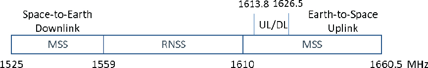
MSS space-to-Earth downlinks are from 1525 to 1559 MHz, and MSS Earth-to-space uplinks are from 1610 to 1660.5 MHz, with a downlink allocation also from 1613.8 to 1626.5 MHz. The L5 band is centered at 1176.45 MHz. RNSS is from 1559 to 1610 MHz.4Figure 1-1 depicts these allocations.
Within the MSS allocations, licenses are assigned to particular users. MSS licensed frequency bands under consideration are shown in Figure 1-2 and include
- Ligado:
- 1526–1536 MHz (downlink)
- 1627.5–1637.5 MHz (uplink)
- 1646.5–1656.5 MHz (uplink)5
- 1670–1680 MHz (proposed downlink)
NOTE: DL, downlink; UL, uplink.
___________________
1 International Telecommunication Union, 2020, “Radio Regulations Articles Edition of 2020,” item 1.25.
2 International Telecommunication Union, 2020, “Radio Regulations Articles Edition of 2020,” item 1.43.
3 International Telecommunication Union, 2020, “Radio Regulations Articles Edition of 2020,” item 1.9.
4 National Telecommunications and Information Administration, 2017, Manual of Regulations and Procedures for Federal Radio Frequency Management, Washington, DC: U.S. Department of Commerce, September.
5 Federal Communications Commission, 2020, FCC Order 20-48, Order and Authorization, April 22; hereafter, FCC Order 20-48.
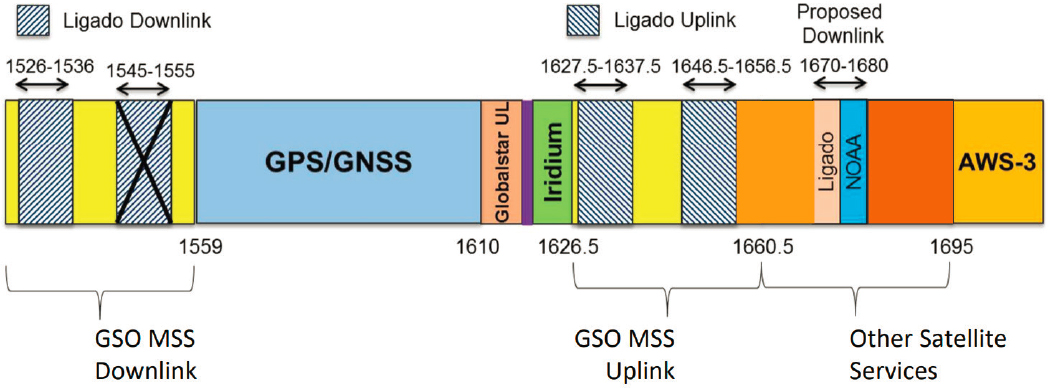
NOTE: AWS, Advanced Wireless Services; GNSS, Global Navigation Satellite System; GSO, geostationary orbit; MSS, mobile satellite services; NOAA, National Oceanic and Atmospheric Administration; UL, uplink.
SOURCE: Coalition of Aviation, SATCOM, and Weather Information Users, “Impact of Ligado’s Proposal on SATCOM, Aviation and Weather Data Users,” Notice of Exparte, FCC Proceedings IB 12-340 and IB 11-109, Coalition Deck for Sept. 4 2019 FCC meeting, posted September 9, 2019, https://www.fcc.gov/ecfs/document/10906015584180/3.
- Iridium: 1617.775–1626.5 MHz (uplink and downlink)6
- Globalstar: 1610–1618.725 MHz (uplink)
- Inmarsat: 1626.5–1660.5 MHz (uplink)
The GPS band specifically under consideration is the L1 signal centered at 1575.42 MHz with a bandwidth of 30.69 MHz (1560.075–1590.765 MHz).7
An additional element in the general description of MSS is the introduction of a service called Ancillary Terrestrial Component (ATC), which permits MSS licensees to operate, if approved and licensed, terrestrial base stations and mobile terminals for the purpose of filling gaps in service areas.8 Ligado was granted authorization for ATC operations in its MSS-licensed bands.9
___________________
6 M. McLaughlin, 2021, “Iridium Communications Inc. Letter Regarding NAS Committee Members [DEPSCSTB-21-02]—Review of FCC Order 20-48 Authorizing Operation of a Terrestrial Radio Network Near the GPS Frequency Bands,” letter submitted to the Committee to Review FCC Order 20-48, Washington, DC: National Academies of Sciences, Engineering, and Medicine.
7 Interface Control Working Group, 2021, “NAVSTAR GPS Space Segment/Navigation User Interfaces,” IS-GPS-200 Revision M, April 13, approved May 21, El Segundo, CA: SAIC.
8 National Telecommunications and Information Administration, 2021, Manual of Regulations and Procedures for Federal Radio Frequency Management, Washington, DC: U.S. Department of Commerce, Chapter 4c, pp. 4–236. US380 In the bands 1525–1544 MHz, 1545–1559 MHz, 1610–1645.5 MHz, 1646.5–1660.5 MHz, and 2483.5–2500 MHz, a non-federal licensee in the mobile satellite services (MSS) may also operate an ancillary terrestrial component in conjunction with its MSS network, subject to the Commission’s rules for ancillary terrestrial components and subject to all applicable conditions and provisions of its MSS authorization.
9 See FCC Order 20-48. It should be noted that the order authorizes a nationwide network, not merely “filling in the gaps.”
1.1.3 In-Band and Out-of-Band Concepts
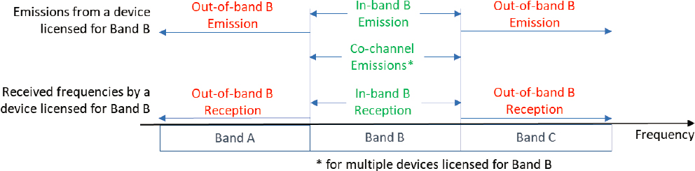
Of particular importance to the efforts under FCC Order 20-48 are the concepts of in-band emissions, in-band reception, out-of-band emissions, and out-of-band reception:
- In-band emissions—emissions at a frequency or frequencies for which an emission is licensed or otherwise authorized.
- In-band reception—emissions received at a frequency or frequencies for which a system is licensed or otherwise authorized.
- Out-of-band emissions (OOBE)—emission at a frequency or frequencies immediately outside the licensed band, but excluding spurious emissions.10
- Out-of-band reception (OOBR)—emissions received from beyond the licensed or otherwise authorized frequencies of a system.
These concepts are depicted in Figure 1-3.
In-band emissions are radiated emissions from devices that are licensed to transmit in the particular band of interest. For example, a Ligado base station transmitting in its MSS/ATC licensed downlink band of 1526–1536 MHz is creating an in-band emission.
Emissions, however, may not necessarily be confined to the band of interest. Owing to equipment design and limitations of active and passive electronic components within the equipment, in practice, equipment may radiate emissions beyond its designated band. These emissions are referred to as OOBE. These emissions are typically unintended and unwanted, and thus are often regulated to not cause interference to devices beyond their in-band frequency range.
Similarly, for equipment receiving a signal, equipment design and limitations of the electronics may allow emissions that are beyond the assigned in-band frequency range to be received by a device. An authorized in-band emission in an adjacent or nearby band may be received by devices that are receiving beyond their licensed band. This is termed OOBR and is generally undesirable depending on the adjacent or nearby band activity.
1.1.4 In-Band and Out-of-Band Considerations
Specific to the efforts under FCC Order 20-48 are emissions from Ligado’s equipment in its licensed bands (in-band emissions) and beyond its licensed bands (OOBE). Regulatory limits on power levels have been established for Ligado emissions both in its licensed bands and beyond its licensed bands. Considerations under the order include the effects
___________________
10 International Telecommunication Union, 2020, “Radio Regulations Articles Edition of 2020,” item 1.144.
of Ligado’s compliant in-band emissions and compliant OOBE on users in the adjacent or nearby GPS band and MSS bands. If Ligado’s equipment complies with its regulatory limits, the fundamental question is how are other users that are nearby in frequency affected?
1.2 GPS OVERVIEW
1.2.1 Background—Global Positioning System
GPS services are critical to modern society, providing coarse (5-m resolution) positioning information to billions of users, including emergency services, aviation, and travel route navigation. In addition, GPS provides attitude and precise timing for some users. More sophisticated use of GPS signals allows commercial services and scientists to locate objects with better than centimeter precision using carrier phase measurements.11 Last, GPS is a critical technology employed in the defense of the United States and its allies.
GPS services consist of a space segment of approximately 32 satellites (space vehicles, SVs) in medium Earth orbits (~20,000 km altitude), so there are about 8 satellites “in view” at almost all locations on Earth at any given time. Each SV has a unique identifier or space vehicle number (SVN).
GPS signals are transmitted in three bands:
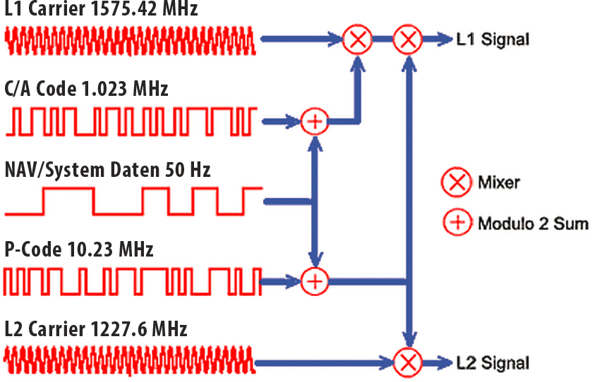
- L1 is centered on 1575.42 MHz, and transmitted signals are contained within a bandwidth of about 30.69 MHz.12 L1 carries both civilian (L1 C/A) and military signals (L1 P(Y) and L1 M code), as depicted in Figure 1-4.
___________________
11 P. Misra and P. Enge, 2011, Global Positioning System: Signals, Measurements, and Performance, Lincoln, MA: Ganga-Jamuna Press.
12 See the GPS Interface Specification, IS-GPS-200M (Interface Control Working Group, 2021, “NAVSTAR GPS Space Segment/Navigation User Interfaces,” IS-GPS-200 Revision M, April 13, approved May 21, El Segundo, CA: SAIC, https://www.gps.gov/technical/icwg/IS-GPS-200M.pdf).
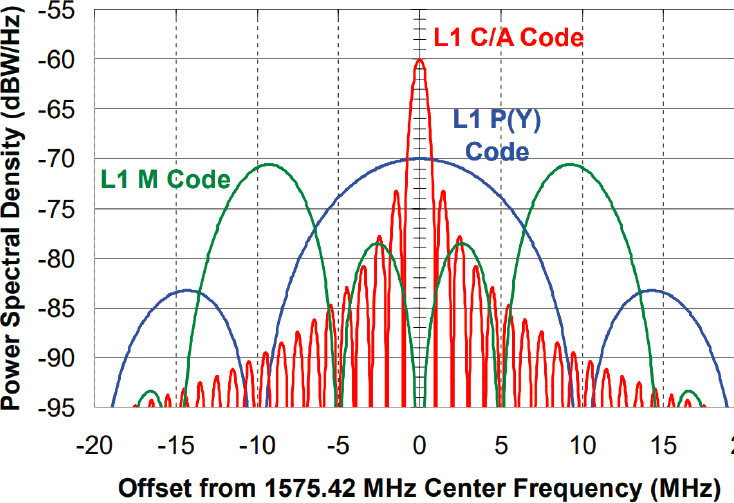
SOURCE: Underlying image from U.S. Geological Survey, 2004, “Improving the GPS L1 Signal,” presentation to the National Space-Based Positioning, Navigation, and Timing Advisory Board, April, https://www.gps.gov/multimedia/presentations/1997-2004/2004-04-ieee/5-ImprovingTheGPSL1Signal.pdf.
- L2 is centered at 1227.6 MHz and carries civilian (L2 C) and military (L2 P(Y), 20.46 MHz bandwidth, and L2 M, 30.69 MHz bandwidth) signals.
- L5 is centered at 1176.45 MHz and carries a civilian signal (L5 and Q5, 20.46 MHz bandwidth).
A new civilian signal on L1 (termed L1 C) is currently operating on five satellites. It occupies 30.69 MHz, with a 4 MHz wide main lobe and significant side lobes out to 14 MHz.
For typical users, a minimum of four GPS satellites are needed to obtain a navigation fix; precision and accuracy can be improved if the user enjoys reception from more than four satellites. The navigation fix is based on measured pseudo-ranges, which are determined by subtracting the transmission time from the reception time and multiplying this difference by the speed of light in a vacuum. Pseudo-range is a combination of true range, transmitter and receiver clock offset effects, effects from signal slowing in the Earth’s ionosphere and neutral atmosphere, and multipath-induced spreading of the signal arrival time. A navigation fix first corrects for each satellite clock offset by using SV transmitted clock calibration data and for ionosphere and neutral atmosphere delay by using models. The receiver clock offset is estimated along with the navigation coordinates, which is why four or more satellites are needed.
The actual received signal power depends on many conditions at the observing site, including the elevation angle of the satellite above the horizon, obstructions, and multi-path interference.
1.2.2 Military GPS Evolution and Policy
On May 23, 1983, when the Navstar GPS satellite production contract was signed, the payload provided wideband encrypted signals on L1 (1575.46 MHz) and L2 (1227.6 MHz) and the unencrypted coarse/acquisition (C/A) signal on L1. Early military GPS receivers were not capable of acquiring the encrypted wideband signals directly given the limits of receiver electronics in those days. Those receivers first acquired GPS through the narrowband, unencrypted L1 C/A signal, which could be easily jammed or spoofed.
The Soviet Union shot down Korean Airlines (KAL) Flight 007 on September 1, 1983. On September 16, 1983, President Ronald Reagan’s Deputy Press Secretary Larry Speakes announced, “The President has determined that the United States is prepared to make available to civilian aircraft the facilities of its Global Positioning System when it becomes operational in 1988.”
Ultimately, the L1 C/A and P(Y) and L2 P(Y) became the Precise Positioning Service (PPS). The unencrypted L1 C/A was designated the Standard Positioning Service (SPS) to fulfill President Reagan’s promise to civil aviation and for civil and commercial use in general.
As technology advanced, the GPS Joint Program Office began development of a Selective Availability Anti-Spoofing Module (SAASM) in the mid-1990s, which enabled military GPS receivers to acquire L1 P(Y) or L2 P(Y) directly and securely.
Chairman of the Joint Chiefs of Staff Instruction (CJCSI) 6140-01A, “Navstar Global Positioning System (GPS) Selective Availability Anti-Spoofing Module (SAASM) Requirements,” dated March 31, 2004, mandated GPS PPS SAASM-based military receivers for all new procurements after October 1, 2006.
In response to concerns about potential electronic warfare threats, Vice President Al Gore announced plans to modernize military GPS at a March 29, 1996, congressional hearing. The U.S. Department of Defense (DoD) started development of a new military satellite signal, M-Code, along with upgrades to the ground control system to manage the new military signal, and military GPS user equipment with upgraded cybersecurity and antijam capabilities in the summer of 1997.
The first GPS satellite to transmit M-Code was launched on September 26, 2005, and it is still operational. According to the Air Force Fiscal Year (FY) 2023 Budget Submission, Initial Operational Capability (IOC) of Operational Control System (OCX) Blocks
1 and 2, which allow the GPS ground control system to fully operate M-Code, is now planned for the first quarter of FY 2024 and M-Code Military GPS User Equipment (MGUE) Increment 1 Lead Platform Integration and Test is scheduled for completion in the second quarter of FY 2025 with Enterprise M-Code Positioning, Navigation, and Timing (PNT) IOC declaration planned shortly after.
With respect to DoD use of non-U.S. military PNT, the relevant DoD instruction states:
- Reliance on civil, commercial, or foreign sources as the primary means of obtaining PNT information for combat, combat support, or combat service support operations is not authorized without a waiver in accordance with CJCS Instruction (CJCSI) 6130.01G. These systems may be utilized as complementary sources, subject to successful NAVWAR compliance determination.
- Use of civil, commercial, or foreign sources to obtain PNT information for non-combat operations is authorized, subject to successful NAVWAR compliance determination.13
1.2.3 GPS Satellites and Transmitted Signal Structure
GPS signals are broadcast in three frequency bands. The L1 signal is transmitted in the band centered on 1575.42 MHz, as depicted in Figure 1-4. The L2 band is centered on 1227.6 MHz. Last, the L5 band is centered on 1176.45. Because Ligado’s downlink is between 1526 and 1536 MHz, its impact is primarily relevant to the L1 band.
The actual L1 signal for Block II satellites14 is
s(t) = AcC(t)D(t) sin (ωct + θ1) + ApPΥ(t)D(t) cos (ωct + θ2) + AmM(t) cos (ωct + θ2),
where C(t) is the coarse acquisition code; D(t) is the navigation signal consisting of clock corrections, ephemeris, and almanac, amounting to about 37,500 bits of data broadcast once every 12.5 minutes, with the most important data constituting less than 1,500 bits and broadcast once every 30 seconds; PY(t) is the military precision ranging code (an encrypted version of the known P(t)); and M(t) is a newer encrypted military code.
The C/A signal (the first term in s(t) above) is composed of a digital navigation data stream (D(t) above) broadcast at 50 bits per second multiplied by a “chipping” code
___________________
13 U.S. Department of Defense, 2020, “DoD Instruction 4650.08: Positioning, Navigation, and Timing (PNT) and Navigation Warfare (NAVWAR),” Change 1, December 30, Washington, DC, https://www.esd.whs.mil/Portals/54/Documents/DD/issuances/dodi/465008p.pdf?ver=M9B6zSt5uWSeDoPwocp_RQ%3D%3D.
14 Block III satellites also broadcast the L1C signal.
(C(t)) with a frequency of 1023 million chips per second). The navigation data stream and chipping code are synchronous. The binary symbols in the time series C(t)D(t) are modulated into the 1575.42 MHz L1 carrier using Binary Phase Shift Keying (BPSK). The chipping code provides noise immunity so that the navigation code can be reliably received and demodulated at GPS receivers; in addition, the chipping code is SVN dependent, so individual SV signal streams can be distinguished. Most importantly, the chipping code provides the absolute ranging capability that enables the determination of pseudo-range, which is the fundamental measurement that underpins standard GPS radionavigation.
The legacy L1 C/A navigation message consists of 37,500 message bits and is transmitted at 50 bits per second. This message is composed of 25 pages of 30 seconds duration, and thus takes 12.5 minutes to transmit. Every page is further subdivided into five 6-second sub-frames; every sub-frame consists of ten 30-bit words.
The content of the navigation message is as follows. Each sub-frame begins with the telemetry word (TLM), for synchronization. It is followed by the transference word (HOW), which provides time information that allows the receiver to acquire the week-long P(Y)-code segment. Sub-frame 1 contains the satellite clock information and information about satellite health. Sub-frames 2 and 3 contain satellite ephemeris. Sub-frame 4 provides ionospheric model parameters, Universal Coordinated Time (UTC) information, and part of the almanac. It also indicates whether anti-spoofing, A/S, is activated. Sub-frame 5 contains the constellation status and data from the almanac, allowing a receiver to more rapidly acquire the satellites. Twenty-five frames are required to complete the almanac.
Sub-frames 1, 2, and 3 are transmitted as part of every frame, and the content of sub-frames 4 and 5 is common across all satellites. Thus, almanac data for all satellites in orbit can be obtained from a single tracked satellite.
The legacy L1 C/A Navigation Message—time parameters and clock corrections, ephemeris parameters, almanac, as noted above, along with Service Parameters with ionospheric model parameters and satellite health information—allows the position of any satellite in the constellation to be calculated. The ephemeris and clocks parameters are normally updated every 2 hours, and the almanac is updated at least every 6 days.
When a receiver successfully demodulates the ephemeris and clock correction parts of the navigation message from four separate GPS satellites, it can use the message contents to calculate the position of the receiver (i.e., latitude, longitude, and height above the Earth’s sea-level ellipsoid). This calculation generally provides positioning accuracy of no worse than 5 m, but accuracy can be further improved by data from the Wide Area Augmentation System (WAAS). High-precision receivers use carrier phase
observations and better models to achieve centimeter accuracy and are discussed further in Section 1.2.5. Averaging over time can often improve accuracy to the order of millimeters for high-precision receivers.
The L1 C/A chipping code is a 1023-bit pseudo-random subset of a Gold code (which can be calculated using two linear feedback shift registers) particular to an SVN. The chips can be denoted as ci = ±1, i = 1, 2, …, 1023, and a navigation message bit as b = ±1. After chipping, b is represented by 1023 bits of the form mi = bci, where mi is BPSK modulated onto the 1575.42 L1 carrier, as indicated in Figure 1-5. A receiver can replicate the chipping code given the SVN and can align its replica chip streams by cross-correlating with the received values mi. The receiver may not know the visible SVNs a priori and so it guesses the SVN and selects the candidate SVNs with the best signal autocorrelation among the trial SVNs. This is part of the process of code acquisition. Chipping, or direct sequence spread spectrum (DSSS), and the associated de-spreading computations in a receiver via code wipe-off greatly improves the effective signal-to-noise ratio (SNR) of a GPS signal, providing robust noise immunity.
SOURCE: P.H. Dana, 1994, “The GPS Overview,”The Geographer’s Craft Project, University of Colorado Boulder, https://foote.geography.uconn.edu/gcraft/notes/gps/gps_f.html.
Robust noise immunity is critical for GPS performance because the observed power levels at the surface of the Earth are on the order of −160 dBW.15 Given a device antenna gain of 4 dBi, the received power, from a satellite near zenith, is about −155 dBW, while the noise power over the 2.046 MHz signal bandwidth is about −140 dBW. Of course, signal power degrades as elevation decreases, but there are usually four or more satellites visible at an elevation of 30 degrees or higher. More detailed signal models that incorporate the effect of satellite elevation and ionospheric interference can be found in Misra and Enge.16 A key observation is that the thermal noise power at a receiver on Earth is higher than signal power.
The legacy L1 C/A signal pseudo-random noise (PRN) code, modulation technique, data rates, data format, and information content were developed in the early 1970s based on the receiver and information system technology of that era as well as projections of how GPS military receivers might operate given those limitations. Twenty-five years later, in the mid-1990s, when DoD initiated the military GPS modernization program, to include M-Code, the GPS Joint Program Office (JPO) realized that receiver technology and connectivity had progressed to the point that a static 37,500-bit message, transmitted at 50 bits per second, and taking 12.5 minutes to receive, was inefficient, was militarily ineffective, and made military receivers vulnerable to exploitation because L1 C/A is unencrypted. M-Code adopted a signal structure that employed modernized modulation techniques, data rates, data format, information content, and flexible messages that were 1,000 times shorter and could be changed by the GPS ground control system so that receivers could receive the information needed much faster. The first M-Code Interface Control Document describing these features was formally published on August 24, 2001. In parallel with its work on M-Code, the GPS JPO proposed using new, more robust PRN codes and different data rates as well as shorter, flexible data messages on L2 similar to M-Code, naming the new signal L2C. On August 17, 2001, the U.S. Department of Transportation (DOT) agreed to this approach and requested the GPS JPO begin implementation of L2C. Shorter, flexible data messages and more robust PRN codes were previously implemented on L5 as well as L1C. Unlike L1 C/A, L2C, L1C, and L5 also have data-less pilot channels that increase performance and interference protection. Nevertheless, a great majority of civilian receivers, including all certified aviation receivers,17 still rely on the L1 C/A code and its 50 Hz navigation data
___________________
15 See Table 3-Va in Interface Control Working Group, 2022, “NAVSTAR GPS Space Segment/Navigation User Interfaces,” IS-GPS-200 Revision M, April 13, approved May 21, El Segundo, CA: SAIC, https://www.gps.gov/technical/icwg/IS-GPS-200M.pdf.
16 P. Misra and P. Enge, 2011, Global Positioning System: Signals, Measurements, and Performance, Lincoln, MA: Ganga-Jamuna Press.
17 RTCA, Inc., 2006, “Minimum Operational Performance Standards for Global Positioning System/Wide Area Augmentation System Airborne Equipment,” RTCA-DO-229-Revision D, Washington, DC, December 13.
stream and cannot operate without this signal and its navigation data. Complete definitions of the GPS downlink Navigation Signals can be found in the applicable GPS interface specification documents.18
Neither L1C, L2C, L5, nor M-Code have been declared operational by the U.S. Space Force. Twenty-four operational satellites are typically required for that to occur. As of April 12, 2022, there are 4 GPS satellites broadcasting L1C, 23 broadcasting L2C, 16 broadcasting L5, and 23 broadcasting M-Code. In its FY 2023 budget request to Congress, U.S. Space Force shows M-Code, L2C, and L5 IOC as the first quarter of FY 2024.
1.2.4 GPS Receivers
The design of a notional GPS receiver is depicted in Figure 1-6. The radio frequency (RF) or analog stage of the GPS receiver consists of the blocks from the antenna through the analog-to-digital (A/D) converter, and the digital stage begins after the A/D. In practice, receivers can be much more complicated, with multiple intermediate frequency (IF) stages. In addition, some receivers perform additional filtering after the signal is digitized.
GPS receivers are specialized. There are general location/navigation receivers (GLNs) such as those in a portable GPS unit, cellular receivers (CELs) such those in a cell phone, and timing (TIM) and high-precision (HP) receivers that use carrier phase measurements to improve accuracy. HP receivers come in several varieties. Those operating
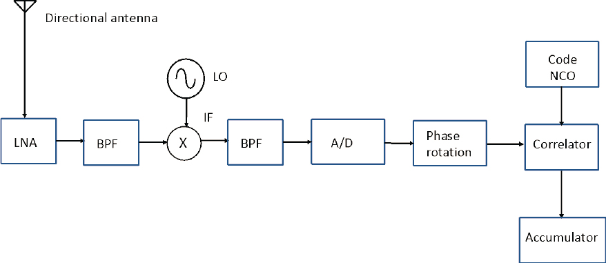
NOTE: A/D, analog-to-digital converter; BPF, band-pass filter; IF, intermediate frequency; LNA, low noise amplifier; LO, local oscillator; NCO, numerically controlled oscillator; the circle with an “x” is a mixer.
___________________
18 L1 P(Y), L2 P(Y), L1 C/A and L2C in IS-GPS-200; L1 and L2 M-Code in ICD-GPS-700; L5 in IS-GPS-705; and L1C in IS-GPS-800.
in real time use software that can produce the needed high precision in real time. To achieve very high accuracy, the same equipment can be used by scientific users that might opt to analyze these data at longer cadences (e.g., hourly or once per day).
The filters have the important job of selecting, to the extent possible, received power only in the band of interest (1560–1591 MHz for L1), so as to receive only the signal that is desired to be processed. For example, for L1 C/A processing, a receiver might employ a narrow filter with a bandpass of about 2 MHz; by contrast, M-code processing might employ a filter with a 20–30 MHz bandpass. A perfect filter would eliminate all power outside the band of interest or “co-channel.” Filters are not perfect; some power in nearby frequency bands makes its way to the final processed digitized signal, although in attenuated form. In principle, with good enough filters, signals away from the co-channel in frequency do not interfere with receiver performance. A well-designed receiver substantially eliminates power from bands outside the co-channel, presenting a “clean signal” for later signal processing.
Another possible issue caused by out-of-band power is desensitization of the initial LNA owing to nonlinear compression if it receives too much input power. The risk for this is elevated in a multiband receiver where a single antenna and LNA have been designed to receive, say, L1, L2, L5, Galileo, and GLONASS signals. If the Ligado signal were to send the LNA of such a receiver into compression, then the remedy would be to add a notch filter between the antenna and the LNA in order to attenuate the Ligado band. This filter would reduce the sensitivity and SNR of the affected receiver, but it could preserve the receiver’s ability to operate in the presence of Ligado signals.
As will be discussed further below, under the FCC order, co-channel interference from Ligado mobile terminals is limited to −105 dBW/MHz throughout the co-channel or band of interest. Ligado interference in adjacent channel is limited to −85 dBW/MHz near the co-channel. With appropriate filtering, the adjacent power, at the license specified levels, in the vast majority of existing GPS receivers does not have a material adverse effect on receiver circuits processing GPS signals; in addition, practical receiver performance characteristics of the sort recommended in later sections of this report can ensure that this is the case.19
The increase in effective noise density is often calculated as (I + N0)/N0, where N0 is the ambient noise power and I is the interference power in a frequency range experienced at the receiver from an unwanted signal. A 1 dB C/N0 signal degradation
___________________
19 The FCC does not generally specify expected receiver characteristics calculated to eliminate the possibility of adjacent (or distant) band interference levels. However, certified receivers, such as those used in aviation, do have such associated requirements. Past FCC studies have recommended that the FCC publish such receiver performance characteristics, as the committee does later in this report.
corresponds to (I + N0)/N0 of 1.259, meaning that the unwanted signal contributes an additional 26 percent over the noise floor to the effective noise power. A 3 dB C/N0 signal degradation corresponds to (I + N0)/N0 of about 2, meaning the unwanted signal contributes an additional 100 percent. A 5 dB C/N0 signal degradation corresponds to (I + N0)/N0 of about 3.2, meaning the unwanted signal contributes an additional 220 percent.
Under test conditions, many GPS CEL receivers tolerate20 noise equivalent to an 8 dB C/N0 signal degradation. Almost all GPS receivers operating in open-sky conditions, including most HP receivers, tolerate noise equivalent to a 4 dB C/N0 signal degradation, or six times the equivalent of a 1 dB C/N0 signal degradation before the onset of harmful interference.
The additional interference power in a frequency band (I above) at a receiver is dependent not only on the power of an emitter, the directionality of the transmitting and receiving antennas, and the “sharpness” of an emitter’s transmission filter, but also on the distance between the emitter and the transmitter. Because received power declines as the square of the distance between the emitter and the receiver for a free-space model, and by a power as high as 3.5 for other models, this has a more profound effect on interference than transmission power. For example, using the free space loss model, if a receiver experiences a 100 percent increase in interference power (over the noise floor) at 3 m from an emitter, it will experience only a 25 percent increase at 6 m of separation and a 1 percent increase in interference power over the noise floor at 30 m of separation.
C/N0, as presented at an antenna, is difficult to measure directly. Rather, the laboratory experiments conducted to evaluate interference available to the committee employ receiver reported C/N0 to estimate the effect of Ligado emissions. Receiver reported values are subject to the device’s opaque, proprietary algorithm and could respond non-linearly, logarithmically, or otherwise. This is often referred to as “effective C/N0.” Effective C/N0 is an explicit measure of the result of interference on GPS receiver functions. It is for this reason that effective C/N0 is the standard figure of merit used by experts in the field to measure receiver health. Receiver reported C/N0 values are, of course, receiver dependent. These figures include receiver noise and processing noise as well as adjacent power caused by RF front-end limitations. Using receiver reported C/N0 greatly complicates the analysis of noise from Ligado emitters, because it requires careful testing of each unit. Nevertheless, almost all of the available studies use receiver reported C/N0 degradation as the figure of merit for the onset of interference.
___________________
20 “Tolerate” here means it suffers no significant degradation in observable performance like position accuracy, acquisition time, or loss of tracking.
GPS acquisition refers to the receiver’s process of aligning its replica chipping code to the SV transmission, determining the Doppler shift of the received carrier signal, or “locking” onto the signaled bit stream. To decode the navigation signal, the receiver must maintain alignment with the C/A code (or the P(Y) code in a military receiver). Acquisition is affected first and foremost by the effective SNR of the transmitted signal at the receiver, which, in turn, affects the quality of the signal presented to the A/D by the RF front end of a GPS receiver. This is a rather receiver-dependent process. If, for example, a receiver admits too much power from adjacent channels, the signals will be much noisier and harder to demodulate and to track.
After digitization, additional signal processing is performed. For example, Doppler frequency shifts caused by the relative motion between the SV and the receiver are corrected. The signal is demodulated, and it is here that the C/A code tracking and carrier phase tracking is performed. This signal processing for the navigation/timing solutions is described briefly below. How interference can adversely affect this processing is discussed later in this report.
Most GPS users rely on pseudo-range observables and the broadcast orbits and clocks corrections. A simplified observable equation for a pseudo-range signal received on the L1 frequency p1(tr) can be defined as:
The first (and largest) term here is true range derived from the three-dimensional coordinates of the satellite, , when the signal was sent, tS, and the receiver position when it was received, . Navigation users rely on the GPS ephemeris provided on the signal itself to model , which is currently approximately 1 m in precision in a radial sense. The satellite clock offset (δs) is also provided in the broadcast ephemeris and is of similar precision. Fairly crude models can be used to remove most of the tropospheric ρt and ionospheric ρi1 effects. For simplicity, the multi-path effect, ρm1, is not discussed here. The measurement noise term is ερ1 (1–2 m). This leaves a navigation user with four unknowns: the receiver’s three-dimensional position and the receiver clock offset (δr). If pseudo-range observations from four or more satellites are available, these four terms can be estimated.
From one SV, a GPS receiver A/D samples the signal
where S is the mixed signal power, fIF is the IF frequency, fD is the Doppler frequency shift, δθ is the carrier phase offset, and n(t) is the noise. τ is the signal delay caused by the speed of light signal transport. The received signal is mixed with the receiver’s local oscillator signal cos(2π(fL1 – fIF)t + θIF). θIF is randomly distributed with respect to the incoming signal phase. The GPS receiver’s job is to get an accurate estimate of (τ, fD, δθ).
A GPS receiver generates two reference signals:
where is the receiver estimated signal delay, is the receiver estimated Doppler shift, and is the receiver estimated phase. These signals are, respectively, the in-phase and quadrature reference signals and are often represented by the analytic signal I(t) + jQ(t). These two signals are multiplied by the received signal r(t), and the resulting samples are accumulated into in-phase and quadrature sums. This feedback of such sums allows the receiver to adjust its estimates of , , and so that they closely match the true values of, respectively, τ, fD, and δθ. A good GPS receiver accurately tracks both C/A code alignment and carrier phase alignment. These are the two “tracking loops” in a GPS receiver. Both loops employ numerically controlled oscillators (NCOs).
Accuracy can be improved by way of carrier-phase enhancement. This technique uses the L1 carrier wave, which has a period 1/1540th of the duration of the L1 C/A chipping code rate, providing an additional clock. The code phase error in the normal GPS causes 2–3 m error in position accuracy. Carrier phase enhancement reduces this to 1–2 cm (0.4–0.8 in). Carrier phase enhancement is complicated by the ambiguity caused by full cycle (2π) shifts of a signal. Carrier phase enhancement is required in high-precision receivers.
1.2.5 High-Precision GPS Users and Considerations
The previous section introduced the pseudo-range observable equation on the L1 frequency and outlined a simple description of how the receiver uses these observations to estimate position and timing. High-precision GPS users rely on the same GPS signals, but use carrier phase observations (ϕ1) instead of pseudo-range:
There are three main differences between the pseudo-range and carrier phase equations:
- There is an extra term (N), the carrier phase bias, which is scaled by the signal wavelength λ1. It remains the same for a given satellite pass as long as the receiver maintains lock on the signal. It must be estimated. High-precision GPS users are concerned about loss of lock because each loss of lock requires that this term be re-estimated. Needing to do so severely degrades their position solutions.
- The ionospheric delay ρi1 has the opposite sign as the pseudo-range ionosphere term.
- The carrier phase measurement uncertainty (εϕ1) is nearly two orders of magnitude smaller (1–2 cm) than the pseudo-range measurement uncertainty.
Either pseudo-range or carrier phase observations can be used to estimate the receiver position . However, one cannot directly achieve cm-level positioning using carrier phase data with the broadcast orbits and clocks. Early on, GPS users realized that this problem could be mitigated by using two GPS receivers and estimating “differential” baselines rather than “absolute positions.” This practice is called differential positioning. It is the underpinning of today’s real-time kinematic (RTK) applications. The location of a receiver can be found by combining its data in software with data from the second “base” station. The difference of the two stations’ carrier phase observations is relatively insensitive to satellite orbit errors and atmospheric delay errors, meaning even the crude broadcast orbits can be used. The clock effects are completely removed in this way. Initially users of this technique deployed their own base stations, but today networks of base stations are operated both by the government and commercial entities.
The users of high-precision GPS can be loosely grouped in three categories:
- Surveyors make critical contributions to the national infrastructure and define legal land boundaries. They were early adopters of GPS and are also significant users of Galileo, BeiDou, and GLONASS signals. They primarily use the differential GPS technique, and the GPS receiver is assumed to be stationary. These users require centimeter-level accuracy. This community has especially benefited from software that allows them to quickly (several minutes) estimate their three-dimensional coordinates. The ability to measure land boundaries with this precision and at this speed has obvious commercial implications. Although modern surveyors would not be worried about downloading
- orbits on the GPS signals (e.g., cold starts), they cannot easily tolerate interference leading to loss of lock.
- RTK users employ similar principles as surveyors, but as the acronym suggests, they measure differential baseline parameters in real time. As with the other user groups, RTK users cannot tolerate interference so severe that it leads to simultaneous loss of lock across many channels. RTK is broadly used in the United States, for example in agribusiness, which uses it to locate farming equipment, and the construction industry, which uses it at building sites. They have similar accuracy requirements as surveyors, centimeter level, with the proviso that there are some applications with extremely short baselines (e.g., two antennas on a single vehicle) that could have more stringent requirements.
-
Scientific users of high-precision GPS are mostly geodesists and geophysicists. These users study scientific issues (measuring plate tectonics, determining group deformation caused by earthquakes or volcanic inflation/deflation) that require three-dimensional positions (daily average) with a horizontal precision of around several millimeters. The atmospheric delays on GPS signals (and on those of any other Global Navigation Satellite System [GNSS], such as Galileo, GLONASS, and BeiDou) are used for both climate and forecasting studies by meteorologists and space weather scientists. GPS data are also now used to provide early warnings of such hazards as tsunamis and earthquakes.
Scientific users of GPS signals ignore all models transmitted by DoD (orbits, clocks, ionospheric models) or by receiver manufacturers that sell similar products to their users. There are long-lived geodetic communities (since 1994) that operate GPS (and GNSS) instruments around the world and provide precise orbits and clocks.21 They require the most accurate models for Earth’s orientation in space, the GPS spacecraft, and ground instrumentation (antenna phase centers and gain patterns primarily). They have demanded that receiver manufacturers provide multi-path suppressing antennas with (azimuthally) homogeneous gain patterns. Data used in this community were initially downloaded from Internet sites, but increasingly these data are streamed. Because these users run their sites continuously, cold starts are for the most part irrelevant, but they cannot tolerate interference leading to loss of lock.
___________________
21 See International GNSS Service, 2020, “Homepage,” https://igs.org.
1.3 FCC ORDER 20-48
On April 19, 2020, the FCC adopted FCC Order 20-48,22 authorizing Ligado Networks, LLC, to move forward with deployment and operation of a low-power terrestrial nationwide network in the 1526–1536 MHz, 1627.5–1637.5 MHz, and 1646.5–1656.5 MHz bands.
1.3.1 The FCC’s Analysis in the Order
The FCC order concludes that there are “significant public interest benefits associated with Ligado’s proposed ATC network deployment” as detailed in Ligado’s amended license modification. After considering “the concerns raised regarding potential harmful interference to adjacent band operations,” including general location and navigation devices, certified aviation GPS devices, non-certified GPS receivers, other U.S. government devices, as well as MSS operations, the FCC order concludes that, subject to the various conditions it imposes on Ligado’s ATC authority, granting the license “will promote the efficient and effective use of our nation’s spectrum resources.” The FCC thus granted the license subject to certain conditions, detailed in Section 1.3.2 below.
Ligado entered into a number of so-called co-existence agreements with several equipment manufacturers (Garmin, Deere, Trimble, NovAtel, Topcon, and Septentrio), representing a major share of the market for general location and navigation, high-precision location and navigation, and non-certified aviation location devices. At various times throughout the long process that has led to this approval, several of these companies provided input to the FCC indicating the potential for harmful interference and objecting to the granting of the then-current Ligado application. Bilateral discussion with Ligado led to a series of commitments by Ligado to each company based on specific emission-level requirements and led to each of the co-existence agreements. The analysis presented in the FCC’s final order relies on these agreements to indicate support for approval of the license:
We find that the co-existence agreements that Ligado has reached with each of the manufacturers discussed above are significant and support the Commission’s finding that technical and operational solutions to address concerns about harmful interference to GPS receivers have been developed and that, with appropriate notifications and other conditions (discussed below), these solutions can address other potential
___________________
22 In the Matter of LightSquared Technical Working Group Report (IB Docket No. 11-109), LightSquared License Modification Application (IB Docket No. 12-340), New LightSquared License Modification Applications (IB Docket No. 11-109; IB Docket No. 12-340), Ligado Amendment to License Modification Applications (IB Docket No. 11-109).
harmful interference concerns as Ligado’s terrestrial network operations are rolled out over time.23,24
In reaching its conclusion to grant the license, the order relies on its determination of whether there will be interference and whether such interference meets the definition of “Harmful Interference.” These definitions are crucial to the FCC’s conclusions regarding authorizing the Ligado system.
The analysis in the order presents the two different measures of interference that are at the heart of the first task that this committee was asked to address. The first of these is an operational definition based on the measured performance of a device under test (DUT), that is, at what emission levels is a device under test no longer able to provide the measurements for which it is intended? Those measurements include position and/or timing accuracy, but also may include other key performance indicators (KPIs), such as the capability and timing to (re)acquire, lock, and maintain signal integrity. As an operational measurement of interference, this method can be used only by actual testing of receivers under consideration. The second method to determine interference is to use an “interference tolerance mask.” Typically, this means answering the question of whether a receiver sees a change in the carrier-to-noise density ratio (C/N0) in the presence of the emitted power from the source under question. It is often the case that a −1 dB ΔC/N0 is used as the threshold for interference. As noted previously, these are both measurements of interference and must be interpreted based on the FCC’s definition of Harmful Interference:
Interference which endangers the functioning of a radionavigation service or of other safety services or seriously degrades, obstructs, or repeatedly interrupts a radiocommunication service operating in accordance with [the ITU] Radio Regulations.
Therefore, Section 1.4 of this report provides background and a detailed analysis on the general subject as well as the difference between the technical definition of interference and the operational definition of the harmful interference. This grounding is important as a precursor to the committee’s responses to the questions one and two of the study charter.
___________________
23 FCC Order 20-48, paragraph 34, p. 19.
24 It should be noted that in their presentations to the committee, Garmin and Trimble commented that these legal agreements should not be construed as inferring that all technical issues about potential interference had been resolved to the satisfaction of Garmin and Trimble. Most, if not all, of the equipment manufacturers listed here have filed statements with the FCC to the effect that none of the agreements they signed were on “coexistence” but rather lawsuit settlement agreements. See, for example, the section “The Commission Overstates and Mischaracterizes the Relevance of Ligado’s Agreements with GPS Manufacturers” of the Trimble Petition for Reconsideration filed with the FCC on May 22, 2020.
The FCC order reviews the various test reports performed over the course of the proceedings, including a series of reports from Roberson and Associates (Results of GPS and Adjacent Band Co-Existence Study, May 9, 2016; Final Report: GPS and Adjacent Band Co-Existence Study, June 10, 2016; collectively the RAA Reports); a GPS device testing report commissioned by Ligado and performed by the National Advanced Spectrum and Communications Test Network (NASCTN), titled LTE Impacts on GPS Final Report (the NASCTN Report); and an April 2018 report from the DOT, titled Global Positioning System (GPS) Adjacent Band Compatibility Assessment Final Report (the DOT ABC Report).
The order reviews the details of these reports and presents the findings of those who advocated for or against approval of the license. In particular, the order notes that at a late stage in the Commission’s proceedings it received a letter25 from the NTIA, including an Air Force memorandum to the NTIA’s Interdepartmental Radio Advisory Committee (IRAC). This letter cites a March 2018 report26 from the National Space-Based Positioning, Navigation, and Timing Systems Engineering Forum (NPEF), which provided an assessment of testing methodologies that had been used in these three reports cited above. The NTIA’s letter stated its (the NTIA’s) belief that the Commission “cannot reasonably reach” a conclusion that harmful interference concerns have been resolved.
Section 2.2 of this report, in providing the committee’s response to Task 2 of its charter, discusses the results of the various studies noted above.
In basing its decision to authorize the Ligado license, the FCC stated that consistent with past practices, the technical measurement of a change in carrier-to-noise density does not provide an appropriate connection to the actual impact of interference in performance (and ultimately to harmful interference). Its conclusion rests primarily on the performance-based assessments as detailed in the reports referenced above, on the lack of data-driven objections from potential affected parties, the various co-existence agreements, and Ligado’s commitments to remediation.
1.3.2 Requirements and Conditions on the Authorization
FCC Order 20-48 approved the Ligado amended application to operate subject to numerous requirements and conditions, which are summarized in Box 1-1.
___________________
25 Letter from Douglas W. Kinkoph, NTIA to Ajit Pai, Chairman, FCC, IB Docket No. 11-109, p. 2 (filed April 10, 2020).
26 NPEF, 2018, “Assessment to Identify Gaps in Testing of Adjacent Band Interference to the Global Positioning System (GPS) L1 Band,” https://www.gps.gov/spectrum/ABC/2018-03-NPEF-gap-analysis.pdf.
1.4 HARMFUL INTERFERENCE
Interference of a radio receiver occurs when some other signal affects the received signal in a way that reduces the effective received SNR. Functionally, an emitter causes interference whenever the operation of that device causes any noticeable reduction on the received SNR. There are various mechanisms through which an emitter could cause such a reduction. The most direct method is by emitting power directly into the receiver’s signal band. Adjacent-band emitted power can also cause interference by a variety of mechanisms. Whether or not the interference is harmful to the receiver’s operations depends on the amount of SNR loss and the analog and digital signal processing functions that the receiver must perform.
This section explores further how an out-of-band signal can interfere with a specific receiver. The discussion illuminates the mechanism of harmful interference and informs the analysis of impact of signal characteristics on existing GPS receivers. To ensure clarity, this section focuses on the broader meaning of “harmful interference” and not the FCC-defined term “Harmful Interference.”
1.4.1 Received SNR and Interference Perceived as a Reduction in SNR
One way to understand the effects of SNR in GPS receivers and many other types of receivers is to look at the noisy symbols post correlation—that is, at the point in the signal processing where the Doppler-shifted carrier signal has been mixed out of the signal, any spreading code has been wiped off the signal, and the resulting signal samples have been accumulated. This discussion of SNR provides a cumulative view of any and all interference effects that might be caused by an adjacent-band signal as it enters the receiver’s antenna and affects various stages of the receiver’s RF front-end signal processing.
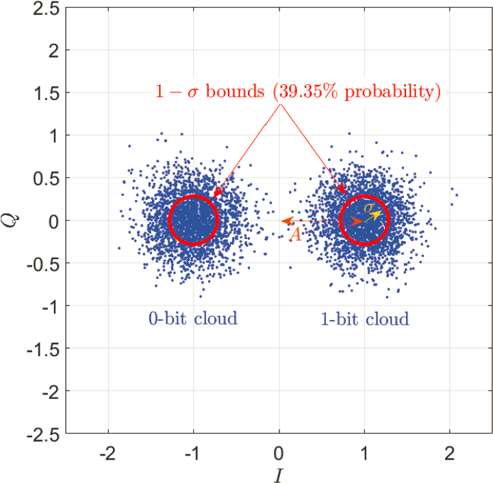
The analytic representation of the resulting noisy symbols are complex numbers of the form I + jQ, where Figures 1-7 and 1-8 plot typical Q versus I point clouds. These are also known as point constellations in the signal processing literature. Figure 1-7 is typical of a GPS receiver that processes a signal that carries navigation data that have been modulated onto the signal using binary-phase shift keying. That is, the digital data are either a 1 bit (phase angle = 0 deg), which centers its cloud on the +I axis when the signal has been phase locked, or a 0 bit (phase angle = 180 deg), which centers its cloud on the −I axis.
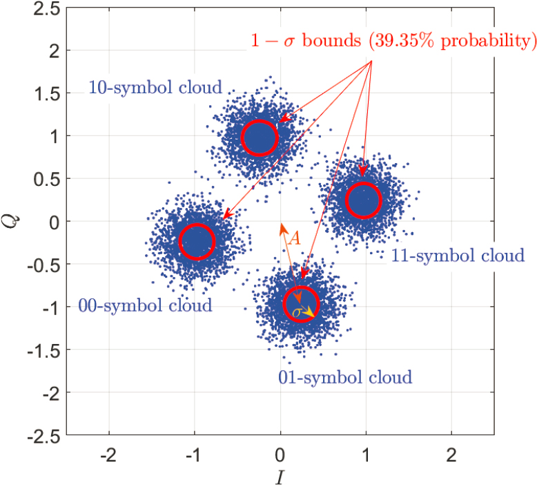
This committee has also been asked to consider the possible interfering effects of Ligado signals on MSS signals, such as Iridium. Figure 1-8 is typical of an Iridium handset processing a signal that carries communication data or navigation data that have been modulated using quadrature phase-shift keying (QPSK). This method encodes 2 bits per symbol. The four point clouds in the figure correspond to the four possible 2-bit combinations. The possible combinations are used to label their respective clouds in Figure 1-8. This figure corresponds to a case where phase-lock has not been achieved, hence the random angle by which the constellation is canted relative to the axes.
SNR depends on the distance of the center of each point cloud from the origin of the (I,Q) plane. This distance is denoted by the quantity A in the two figures. It also depends on the radius of each point cloud that captures 39.3 percent of the points in the respective cloud. This radius is denoted as σ in the two figures. The non-dimensional SNR equals A2/(2σ2). The A2 in the numerator represents the GPS signal’s power. The σ2 factor in the denominator arises from the noise in the I and the Q components, and the factor 2 arises because both noise components impact GPS receiver performance.27 The noise is modeled as being independent and Gaussian in each component with a variance of σ2. Absent the noise, each point cloud would collapse into a single point. Usually, the SNR is given in dB units, which is calculated using the expression 10log10[A2/(2σ2)].
___________________
27 Note that SNR can be split into a bit error SNR and a phase measurement error SNR rather than a single total SNR. In this alternative convention, these two SNRs both equal A2/σ2 rather than A2/(2σ2).
A related quantity is the C/N0. This equals the product of the SNR and the bandwidth, BW = 1/Taccum, where Taccum is the coherent integration time for the symbol(s) or code(s) being detected. Thus, C/N0 = A2/(2σ2Taccum). This quantity is nominally thought to give a good raw measure of the signal power relative to the average power spectral density of the received noise and to be independent of the signal processing within the receiver. As discussed in Section 1.2.4, this quantity is sometimes referred to as effective C/N0. Often C/N0 is given in decibel-Hertz (dB-Hz) units, which is calculated using the following formula: 10log10[A2/(2σ2Taccum)]. The C/N0, SNR, and Taccum values that correspond to the cases depicted in Figures 1-7 and 1-8 are given in their respective captions.
Interference, other than spoofing, manifests itself as a reduction of SNR, or equivalently, a reduction of effective C/N0. The interference acts like added noise so that the receiver reports the value of C/(N0 + I) as though it were C/N0, with I being the effective average power spectral density of the interfering signal as experienced by the receiver at the output of its RF front end. Interference causes a reduction of the ratio A/σ. That
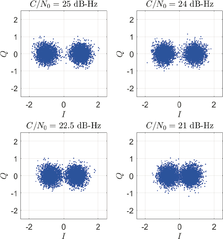
is, the distance of the point cloud centers from the origin gets reduced relative to their diameters. This situation is depicted in Figure 1-9. The upper-left plot is a repeat of Figure 1-7 for a BPSK GPS signal, which assumes C/N0 = 25 dB-Hz. The upper-right plot corresponds to a 1 dB interference-induced reduction of C/N0, the lower-left plot corresponds to a 2.5 dB reduction, and the lower-right plot corresponds to a 4 dB reduction. If the interferer’s power is strong enough or if it is near enough to the GPS receiver, then these levels of C/N0 reduction or even more drastic levels of reduction can occur.
A similar situation occurs if the Iridium-type QPSK signal of Figure 1-8 experiences varying levels of effective C/N0 reduction owing to interference. The four point clouds tend to merge as interference becomes more pronounced.
The effects of interference depicted in Figure 1-9 are shown as reductions in the signal power A2 while the noise power 2σ2 remains constant. This is typically the case at the output of a GPS receiver’s RF front end, where the effect typically manifests itself as an apparent reduction of A2, consistent with the figure. This reduction occurs because a
typical receiver uses automatic gain control (AGC) in a situation where the noise power dominates the signal at the output of the RF front end owing to the spread spectrum nature of GPS signals. As noise-plus-interference power increases, the receiver’s AGC decreases its gain in order to hold the power constant at the output of the RF front end’s analog-to-digital converter (ADC). This AGC adjustment is needed in order to use the limited number of output bits of the ADC in an optimal manner under normal operating conditions.
Other receivers, such as Iridium receivers, may not use AGC. In such situations, the phenomenon of increased interference would manifest itself as an increase of the noise power 2σ2 while the signal power A2 remained constant. In a figure such as Figure 1-8, this would correspond to a widening of the four point clouds while their centers remained a fixed distance from the origin. In either case, the point clouds tend to merge as interference increases.
1.4.2 The Problems That Interference Can Cause for a GPS Receiver
As noted in the FCC Order 20-48, the definition of “Harmful Interference” is:
Interference which endangers the functioning of a radionavigation service or of other safety services or seriously degrades, obstructs, or repeatedly interrupts a radiocommunication service operating in accordance with [the ITU] Radio Regulations.
In order to assess the harmfulness of interference, it is helpful to understand the physical mechanisms by which harm occurs. The progressive effects of increasing interference, as depicted in Figure 1-9, can cause problems for GPS receivers in a number of ways. The first question put to this committee asked whether a given level of SNR reduction or a given level of position accuracy degradation was the best indicator of harmful interference. This reduction of the question of harmful interference to a simple binary choice obscures important aspects of effective GPS receiver operation. There are multiple ways in which interference can degrade GPS receiver operation that defy simple characterization as either a single SNR degradation metric or a position accuracy degradation metric.
Although much of the current discussion is framed in terms of the effects of the impacts of SNR reductions owing to interference, this approach is used as a means of illustrating the harmful effects of interference from a GPS receiver’s viewpoint. Considerations from this viewpoint, however, do not allow the prediction of harmful interference by a single value for a tolerable amount of SNR loss or, equivalently, C/N0 loss.
One problem that can occur for a GPS receiver is an inability to correctly decode the navigation data that are broadcast by the GPS satellites on the signals and that are needed by the receiver in order to compute GPS satellite locations and clock calibration offsets, which are necessary inputs to a navigation solution. As C/N0 decreases and the pairs of point clouds in Figure 1-9 begin to merge, bit error rates increase, and eventually the receiver will be unable to decode the needed data. At this point, the given GPS signal becomes unusable for navigation purposes.
Another problem that is caused by interference concerns degradation of a receiver’s ability to measure the amplitude and phase of the (I,Q)-plane point clouds, as depicted in Figure 1-10. As the effective C/N0 decreases owing to interference, the signal amplitudes Ai and beat carrier phase offsets Δϕi of individual points within a cloud become less and less accurate measures of the amplitude and phase offset of the corresponding cloud center. (Note that the term “beat carrier phase” refers to the difference between the nominal phase that the received signal would have if there were no carrier
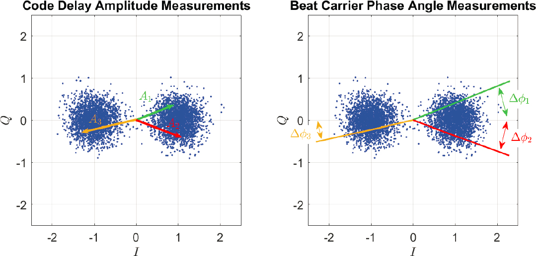
Doppler shift and the actual phase that it has. Thus, the beat carrier phase is the negative of the time integral of the carrier Doppler shift.)
Errors in individual Ai values as measurements of a cloud center’s distance from the origin of the (I,Q) plane translate indirectly into pseudo-random number (PRN) spreading code phase measurement errors by the receiver. The measurement precision of PRN spreading code phase translates directly into pseudo-range measurement precision, which is the fundamental measurement of standard GPS position and time offset determination. Increases in the root mean square (RMS) noise-plus-interference component of a receiver’s navigation error are proportional to increases in the RMS value of the Ai measurement errors expressed as a fraction of the true received value. Thus, the RMS value of the positioning error component is proportional to . Furthermore, if the RMS code phase measurement errors become too large, then the receiver can lose code lock on the signal, in which case it becomes unusable for surveying, scientific applications, and navigation.
Errors in individual Δϕi values as measurements of a cloud center’s rotational orientation relative to the I axis directly affect carrier Doppler shift measurement errors if the receiver uses a frequency-lock loop (FLL). If it uses a phase-lock loop (PLL), then Δϕi measurement errors translate directly into beat carrier phase errors in this loop’s feedback path, and they also affect its estimation of carrier Doppler shift. The measurement precision of carrier Doppler shift translates directly into range-rate measurement
precision, which is the fundamental measurement of standard GPS velocity and time offset rate determination. The measurement precision of the beat carrier phase translates directly into accumulated delta range measurement precision, which is the fundamental observable of high-performance (HP) GPS ultra-precise position and time offset determination. Increases in the RMS noise-plus-interference component of a receiver’s velocity error or its high-precision position error are proportional to increases in the RMS value of the Δϕi measurement errors expressed in radians. Thus, the RMS value of the velocity error component or its high-precision position error component is proportional to . Furthermore, if the RMS frequency or beat carrier phase measurement errors become too large, then the receiver can lose frequency lock or phase lock on the signal, in which case it becomes unusable for navigation.
Even before loss of phase lock, a PLL can start to experience cycle slips. As C/N0 decreases in a given HP receiver, the frequency of cycle slipping increases. These slips are highly detrimental to the performance of an HP receiver because the receiver cannot use the given signal in its ultra-precise position fixes until the integer number of cycle slips has been resolved. This can take minutes. This can cause a delay of minutes to hours in a HP application such as surveying. For the HP application of precise construction site grading using automated earth-moving equipment, the entire operation could be placed on hold because such equipment needs precise position fixes in real time. For the HP application of tsunami prediction, the system would fail to provide any usable data.
1.4.3 The Variability of Tolerable Amounts of C/N0 Loss
The amount of loss of C/N0 that is tolerable depends on the signal and on the receiver’s signal processing architecture. Consider the situation of a clear sky view, negligible adjacent-band interference, and a high-sensitivity receiver that uses a good patch antenna with an embedded LNA. Received C/N0 values for the visible GPS satellites might range from 50 dB-Hz for high-elevation satellites down to 35 dB-Hz for satellites near the horizon. A signal with C/N0 = 50 dB-Hz could easily tolerate an interference-induced degradation of 5 dB. A signal with C/N0 = 35 dB-Hz might be rendered useless by a 5 dB degradation. Thus, the tolerable degradation depends on the likely range of available C/N0 values for the nominal application in the absence of interference. Furthermore, environmental and use factors may consume this link margin—for example, building or foliage obstruction, ionospheric scintillation, or vibration and dynamics. A typical receiver design includes link margin for such situations. It might not have enough margin to handle these design cases along with degradation from Ligado, even if the latter were less than 5 dB.
Furthermore, there can be a lot of variability between receivers of their minimum usable C/N0 values. Recalling Figure 1-10, an obvious thing to do in order to improve both the Ai measurement accuracy and the Δϕi measurement accuracy would be to average the locations of multiple (I,Q) points that were known to lie in the same cloud. If C/N0 gets degraded too much, then the point clouds start to coalesce, and this method can break down. For Assisted GPS (A-GPS), as in the E911 services of smartphones, the point cloud memberships can be known a priori via cellular-network-supplied data, and there is no such problem of proper point/cloud association. A-GPS receivers can operate at very low C/N0 values. Other receivers have hard lower limits of about 20–25 dB-Hz for proper point-cloud association for the GPS L1 C/A codes that form the foundation of much of the currently used civilian GPS.
For various reasons, however, C/N0 in the range 20–25 dB-Hz may not be tolerable for some receivers. They may need to track dynamic signal variations with a high bandwidth. This precludes the use of too much averaging of (I,Q) points before the extraction of Ai and Δϕi measurements. Some receivers cannot use signals with C/N0 values lower than 35 dB-Hz.
Another factor in receiver performance is the number of usable GPS signals. The bare minimum for standard navigation is four. Typical receivers see eight or more signals and use all of them in order to get an improved solution. Interference that caused a 5 dB loss of C/N0 might knock out the four weakest signals but only degrade the accuracy of the other four signals by tolerable amounts. If the geometry of the remaining four satellites is good, then the achieved RMS position error might not be degraded significantly. If the receiver also needed to perform Receiver Autonomous Integrity Monitoring (RAIM), that capability would be lost owing to the lost “extra” satellites. HP applications require far more than the minimum of four satellites in order to achieve mm-precisions and to resolve carrier cycle slips.
Yet another problem with degraded C/N0 is that of signal acquisition, especially cold-start acquisition. Cold-start acquisition involves a brute-force search for signal power above the noise floor in a two-dimensional space of possible carrier Doppler shifts and PRN code delays. For low values of C/N0, the required amount of coherent integration time, Taccum, increases markedly, and this increase forces the use of a finer grid in the Doppler shift search space. The search will eventually take too long or become impossible owing to point/cloud ambiguities. As an example, a given receiver may be able to maintain lock and deduce navigation observables from a signal with a C/N0 value of only 25 dB-Hz, but it might be unable to perform successful cold-start acquisition for a signal with C/N0 less than 35 dB-Hz. Such a problem might not be evidenced in a controlled
test of RMS position error for receivers that experienced interference after they had acquired the GPS signals and successfully transitioned to tracking.
1.4.4 Mechanisms by Which an Adjacent-Band Emitter Causes SNR (and C/N0) to Degrade and the Variability of These Mechanisms Between Receivers
Interference from an adjacent-band emitter manifests itself in a receiver as a noticeable reduction in A/σ when the emitter is turned on or when the receiver comes close enough to the emitter. That is, the point clouds in Figure 1-9 progress from left to right and from top to bottom for a given GPS signal as processed within a given receiver.
There are five mechanisms by which an adjacent-band emitter can cause a reduction in SNR or, equivalently, C/N0. The following discussion of these mechanisms borrows heavily from a paper by Hegarty et al. (2021).28 Four of the five mechanisms are functions of the receiver’s RF front-end design. The second author of the cited paper is an internationally recognized expert in the field of GPS receiver RF front-end design, who has designed front ends for commercial GPS receiver manufacturers and for specialty research applications, among them the FOTON receiver that currently flies on the International Space Station and that has been used to detect a GPS jammer at a Russian base in Syria.29
The most obvious mechanism for impacting C/N0 is the OOBE of the emitter that fall into the GPS band. These emissions contribute directly to the effective average value of N0 in the ratio C/N0. GPS receivers cannot mitigate this component of interference unless it has special properties, such as lying in a narrow frequency band or in a narrow time window. If it is too large and does not have such special properties, then all GPS receivers’ performance will degrade significantly.
The other four mechanisms for an adjacent-band emitter to cause C/N0-reducing interference all involve the GPS receiver allowing adjacent-band signals to enter the GPS receiver pass band directly or indirectly, or they involve the receiver reducing the in-band power of the GPS signal as a by-product of the effect of the out-of-band signal. Two of these mechanisms involve nonlinear effects in the receiver’s RF front end. These nonlinearities exist in the receiver’s LNAs, its mixers, and its other circuitry. Adjacent-band power, if it enters an LNA, can drive the LNA into its nonlinear range where the effective gain gets reduced. This is referred to as compression. This gain reduction affects the in-band GPS signal, thereby reducing the value of the received signal power C in the ratio
___________________
28 C.J. Hegarty, D. Bobyn, J. Grabowski, and A.J. Van Dierendonck, 2020, “An Overview of the Effects of Out-of-Band Interference on GNSS Receivers,” NAVIGATION 67(1):143–161.
29 M.J. Murrian, L. Narula, P.A. Iannucci, et al., 2021, “First Results from Three Years of GNSS Interference Monitoring from Low Earth Orbit,” NAVIGATION 68(4):673–685.
C/N0. Another nonlinear effect is intermodulation. The adjacent-band power may inadvertently get mixed with a signal in another adjacent band owing to receiver nonlinearities, and this spurious mixing may send power into the GPS band, effectively increasing the noise in the GPS band.
The effect known as reciprocal mixing occurs if the mixing signals used by the receiver are not perfect sinusoids. The receiver multiplies these signals by the incoming RF signal and later by intermediate-frequency (IF) versions of the original signal in order to convert it to a lower IF or even to base-band. The output frequency is the difference of the original signal’s RF or IF and the mixer frequency—if the latter is a pure sinusoid. If the mixer has any harmonics, then they could mix with adjacent-band signals in a way that translates those signals into the new IF of the GPS signals. If this happens, then the adjacent-band power gets overlaid on top of the GPS power.
The last mechanism by which adjacent-band power gets translated into the GPS band is simple aliasing. If fs is the sample rate, then the Nyquist band extends from −fs/2 to +fs/2. Any remaining signal components outside this band prior to digital sampling will be shifted into this band via a frequency shift equal to mfs, where m takes on whatever integer value is needed in order to shift the component into this band. Attenuated, adjacent-band power after the final analog processing on the RF front end can get aliased into a digital GPS receiver’s Nyquist band by the sampling of the RF front end’s ADC at some sampling rates. Depending on the receiver, the Nyquist band is typically not much wider than the GPS signal of interest. Under these circumstances, the aliased energy is likely to interfere with the GPS signals.
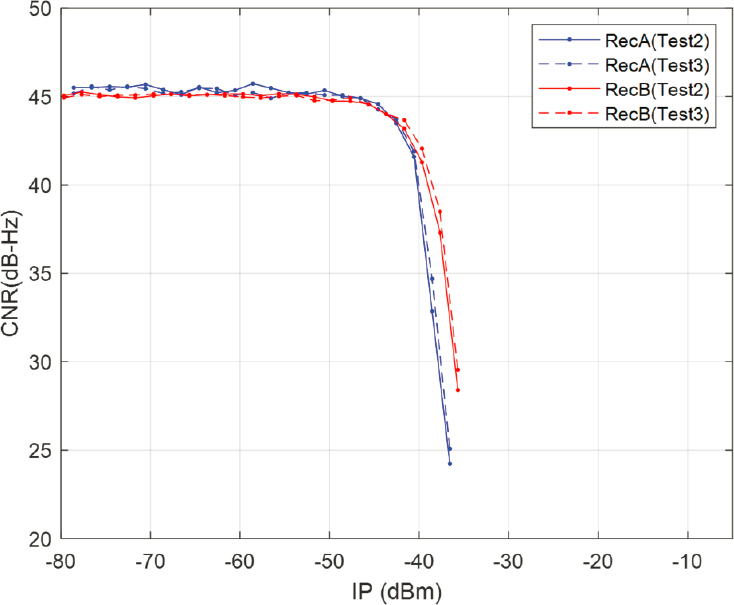
LNA compression and intermodulation, being nonlinear effects, likely will not exhibit a one-to-one relationship to the adjacent-band signal power. Thus, a 1 dB increase in the received adjacent-band power will likely not translate into a 1 dB decrease in C/N0. The decrease may be more or it may be less than 1 dB. This type of loss relationship is illustrated in Figure 1-11, which shows the results from a test that have been supplied by the DOT. The value of C/N0 for received interference powers below −50 dBm does not change. This happens because the effective added noise power spectral density remains negligible relative to the receiver’s nominal N0 owing to thermal noise. Above −40 dBm the C/N0 versus interference power approaches a negatively sloped asymptote, with slope on the order of −10 dB/2 dB = −5 dB/dB. Although it is possible to conclude from this figure that a nonlinear effect such as LNA compression, intermodulation, or some combination of these effects is present for the tested receiver model, it is not possible to make a determination among these causes without detailed information about the particular receiver design’s RF front end.
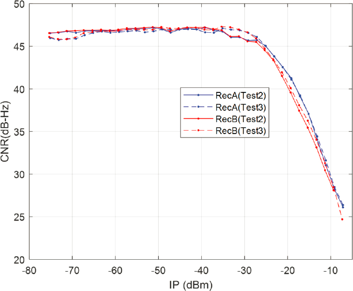
Reciprocal mixing and aliasing, on the other hand, are linear on the adjacent-band signal. Therefore, one would expect the high-interference-power asymptotes of their C/N0 versus noise power curves to have slopes of −1 dB/dB. This is nearly the high-interference-power asymptotic slope for the identical pair of receivers whose DOT-provided test results are shown in Figure 1-12. As with the data in Figure 1-11, it is not possible to know whether this receiver model’s C/N0 degradation results from reciprocal mixing, aliasing, or some combination thereof without detailed information about its RF front end’s design.
1.4.5 Receiver Design Impact on the Ability of Adjacent-Band Power to Impact the Effective C/N0
The four mechanisms by which adjacent-band power impacts GPS C/N0 can be reduced by the designs of the RF front-end electronics. In particular, various stages of bandpass filtering are applied in a typical RF front end. If designed properly, the impact of adjacent-band power can be reduced by many 10s of dB. A good RF front-end designer considers the anticipated adjacent-band power levels and designs the RF front-end LNA,
SOURCE: U.S. Department of Transportation Volpe Center, 2022, “Response to National Academies of Sciences, Engineering, and Medicine Questions,” Document submitted to the Committee to Review FCC Order 20-48, Washington, DC: National Academies of Sciences, Engineering, and Medicine.
SOURCE: U.S. Department of Transportation Volpe Center, 2022, “Response to National Academies of Sciences, Engineering, and Medicine Questions,” Document submitted to the Committee to Review FCC Order 20-48, Washington, DC: National Academies of Sciences, Engineering, and Medicine.
mixing, and filtering scheme appropriately in order for the net impact of all adjacent-band power to be negligible. If the adjacent-band spectrum undergoes changes, as is the case with FCC Order 20-48, an RF front-end design that worked very well pre-FCC Order 20-48 may or may not work well post-FCC Order 20-48.
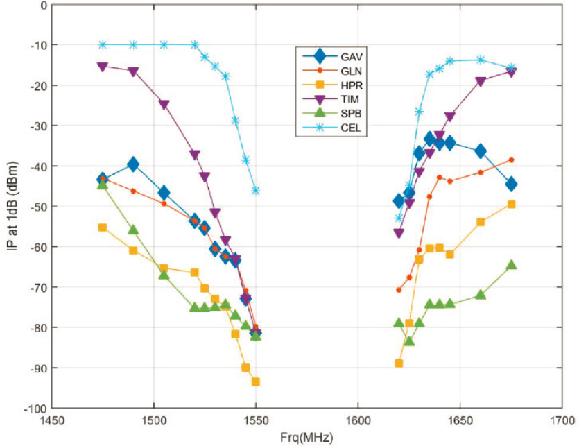
Figure 1-13 plots the adjacent-band power levels that cause a 1 dB C/N0 reduction as functions of the adjacent-band power’s center frequency. The Ligado tower frequency band center is 1531 MHz. The various curves apply to a variety of tested GPS receivers. This plot has been supplied to the committee by the DOT and shows that the power levels required to produce a 1 dB C/N0 reduction in the tested receivers varies from a high of −15 dBm to a low of −75 dBm. Thus, there is a 60 dB variation of receiver susceptibility to interference from Ligado towers as measured using a 1 dB C/N0 loss threshold. This wide variation of sensed interference at each receiver is not owing to Ligado’s out-of-band emissions from the tower that fall within the GPS band, because that mechanism of interference is virtually identical for all GPS receivers. The variations must arise owing to one or the other of the four additional mechanisms by which adjacent-band power can impact GPS in-band C/N0, all of which are highly dependent on the receiver front-end filtering: LNA compression, intermodulation, reciprocal mixing, or aliasing. Which
SOURCE: U.S. Department of Transportation, 2018, United States Department of Transportation Global Positioning System (GPS) Adjacent Band Compatibility Assessment, Washington, DC, Figure 3-22.
mechanism or combination of mechanisms applies to a given receiver cannot be determined from the plot. What is clear is that the best receiver does a much better job relative to the worst receiver of attenuating the Ligado signal before it can affect the GPS in-band C/N0.
1.4.6 Summary Regarding Harmful Interference
Harmful interference of a given GPS receiver owing to an adjacent-band signal occurs when that signal causes the effective C/N0 values of enough signals to degrade by large enough values to degrade the receiver’s performance. The amount by which C/N0 actually gets degraded is highly dependent on receiver design.
Thus, any standard purporting to predict harmful interference must first characterize the power of a potentially interfering signal in specific frequency bands. Limiting interfering power in the RNSS band (1559–1610 MHz with the GPS L1 signals occupying part of this band) is of primary importance to preventing harmful interference; however, interfering power in adjacent frequency bands can also cause harmful interference. The
effect of interference power in adjacent frequency bands diminishes as the frequency of the interfering signal gets farther and farther from the intended reception band. Harmful interference as it affects a receiver is dependent on receiver design; so, any standard that purports to predict harmful interference must make assumptions about “reasonable” receiver designs. Indeed, “certified receivers” do just that. Furthermore, C/N0 degradation can be caused either by increased interference power, decreased signal power, or receiver design; so, it is not a workable regulatory standard for specifying emitter characteristics. However, the foregoing discussion helps us understand the mechanisms of harmful interference on receivers and can lead to a reasonable regulatory standard that specifies tolerable (and intolerable) interference power in specific frequency ranges that include bands that are adjacent to the RNSS band and not just the actual RNSS band.
It is possible to design L1 GPS RF front ends so that the degradation of the effective C/N0 is negligible for the permitted Ligado signal power characteristics even at close ranges. Not all existing GPS receivers have RF front ends that do this, although almost all receivers tested before the Ligado order experienced no harmful interference. In Task 2, the committee examines the likelihood of harmful interference owing to operation of Ligado emitters as specified in the FCC order.
Even for a given level of C/N0 degradation, the question of whether it causes harm is receiver-dependent and application-dependent. For some low-bandwidth applications, a large reduction in C/N0 may be tolerated by the receiver without any significant loss of function. For other receivers, a C/N0 reduction of 4 dB or even less could cause significant harm to performance. This harm could come in a variety of forms. It could involve reduced position accuracy. It could involve increased frequency of cycle slips that degrades the availability of high-precision position solutions or altogether precludes them. It could involve an inability to acquire new signals. It could involve an inability to perform Receiver Autonomous Integrity Monitoring. There is no way to know ahead of time what level of C/N0 degradation may cause harm and how that harm may manifest itself unless one analyzes a particular receiver’s ability to support a particular application.
Even a receiver that can tolerate a large degradation of C/N0 in open-sky conditions may not tolerate a much smaller loss of C/N0 in other situations for which it has been designed. Consider a smartphone receiver that supports Enhanced 911 (E911) service. It is designed to work with very low C/N0 values in order to continue providing location to emergency responders while deep inside a building. That capability would help make it insensitive to the permitted Ligado signals when operating in an open-sky test or the equivalent. Suppose it were operating inside a building that included an indoor Ligado “tower.” The combined reduction in C/N0 owing to being indoors and owing to the Ligado signal could render its E911 geolocation capability inoperable even though it
could have supported E911 service if it only had to contend with being indoors, as per design.
Test results from one receiver manufacturer indicate that their newest high-precision receivers can operate satisfactorily in the presence of the currently approved Ligado downlink power level. Therefore, it is known that the technology currently exists to design GPS receivers for some functions, perhaps some of the most demanding functions, that will not experience harmful L1-band interference from Ligado downlink signals. This has been achieved through proper design of the RF front end to attenuate the Ligado signals sufficiently before they can negatively impact the effective in-band C/N0 to a noticeable extent.
Some receivers, both commercial and DoD, process signals from multiple bands—for example, L1 and L2, or L1, L2, L5, Galileo, BeiDou, and GLONASS. They may use a Kalman filter in order to fuse the various pieces of radionavigation data from the various bands and systems. In some cases, the data from other bands might mitigate harmful interference to data in the L1 band owing to Ligado signals. In other cases, the use of multiple bands may just shift the mode by which Ligado interference on the L1 band harms receiver performance. For example, suppose that an L1/L2 receiver has been configured to use the data from its two frequencies in order to estimate and cancel the ionosphere delay. In that case, interference on L1 owing to Ligado could disable this receiver function so that harm would come in the form of increased receiver navigation error owing to increased ionosphere error. Questions of how Ligado signals might or might not harm multiband receivers have not been deemed to be in detail by the committee. Such questions were considered beyond the scope of its inquiry. Furthermore, receiver testing did not consider such issues.
1.4.7 Definition of Harmful Interference
The FCC included the following definition of Harmful Interference in FCC Order 20-48:
Interference which endangers the functioning of a radionavigation service or of other safety services or seriously degrades, obstructs, or repeatedly interrupts a radiocommunication service operating in accordance with [the ITU] Radio Regulations.
In addition, the FCC uses the following very similar definition from United States Code (USC), Title 47 Telecommunications, Chapter 1, Subchapter A, Part 15, Section 15.3 Definitions:
(m) Harmful interference. Any emission, radiation or induction that endangers the functioning of a radio navigation service or of other safety services or seriously degrades, obstructs or repeatedly interrupts a radiocommunications service operating in accordance with this chapter.
These paragraphs define Harmful Interference for two classes of radiocommunication services: (1) radionavigation and other safety services and (2) all other radiocommunication services.
Two conditions must—per provisions of USC, Title 47 Telecommunications, Chapter 1, FCC, Within the United States and Possessions—be met in each case for a situation to be considered Harmful Interference:
- The emission, radiation or induction must (a) endanger the functioning of the radionavigation or safety service or (b) seriously degrade, obstruct, or repeatedly interrupt any other radiocommunication service; and
- The service claiming Harmful Interference must be operating in accordance with regulations.
The definition of Harmful Interference is effectively the same for the ITU, which regulates international frequency spectrum usage, the NTIA, which manages U.S. federal government use of spectrum, and the FCC, which regulates U.S. commercial as well as state and local government use of spectrum.
Given that there is greater likelihood of loss or life or property when a radionavigation or safety service is interfered with, the threshold conditions for Harmful Interference are lower than those for other radiocommunication services.
GPS operates in the RNSS radiocommunication service, so Harmful Interference, as specified by the FCC, is defined by items 1a and 2. Iridium operates in the MSS, so Harmful Interference is defined by items 1b and 2.
By design, “Harmful Interference” is defined, a priori, in subjective operational terms, rather than technical, objective terms. Also, some interference does not rise to the level of being harmful, as discussed already in this section. The FCC initially evaluates Harmful Interference on a case-by-case basis. This is to allow regulators to balance the relative benefits of competing systems and technologies. In many, but not all instances, once competing and complementary interests are reconciled, technical rules and regulations can be written to define the boundaries of “Harmful Interference” as purportedly accomplished in FCC Order 20-48.
This committee was charged with reviewing whether FCC Order 20-48 actually creates conditions such that no harmful interference will occur as a result of its permitted Ligado emissions. The committee has concentrated on the physics and engineering questions of harmful interference, but not on the strictly legal definitions. Therefore, the committee made no effort to assess whether any RNSS or MSS—for example, GPS and Iridium—were or were not “operating in accordance with [the ITU] Radio Regulations” or “operating in accordance with this chapter.” Instead, the committee proceeded under the assumption that it has been charged with determining whether existing RNSS or MSS would be harmed by Ligado interference independent of any legal ruling about whether they were “operating in accordance with [the ITU] Radio Regulations” or “operating in accordance with this chapter.”


