


Below is the uncorrected machine-read text of this chapter, intended to provide our own search engines and external engines with highly rich, chapter-representative searchable text of each book. Because it is UNCORRECTED material, please consider the following text as a useful but insufficient proxy for the authoritative book pages.
8S e c t i o n 2 The first objective of this study, a review of the nature and quality of the data currently being collected, was achieved through a literature review, a review of relevant definitions used in analyzing bulk package accident performance, an inves- tigation of existing data collection strategies, and an extensive interview process. The literature review focuses on studies and reports in the following categories: ⢠Cargo tank and portable tank classification and specifi- cations. The packages for which accident data will be col- lected are identified, and design attributes are noted, such as minimum head and shell thicknesses and type and location of valves and manholes. ⢠Cargo tank motor vehicle industry practices. Besides con- tainer design specifications, industry practices may influ- ence the performance of cargo tanks in an accident scenario. Factors affecting the service life of a cargo tank that were identified in Bowman et al. (2009) are summarized. ⢠Container performance studies. Past studies were reviewed to determine how existing crash data have been used. For highway cargo tanks, a number of analyses have been per- formed to evaluate the performance of front heads as well as container performance in rollover scenarios. Key factors required to perform similar statistical analyses of container performance are identified. ⢠Cargo tank accident investigations. Accident investigations were reviewed to identify key factors for inclusion in a data- base enabling statistical analyses of container performance. Data collected by existing programs were reviewed for appli- cability in evaluating cargo tank and portable tank perfor- mance in accidents. These existing programs include PHMSAâs Hazardous Materials Incident Reporting System (HMIRS), the FMCSAâs Motor Carrier Management Information Sys- tem (MCMIS), the University of Michigan Transportation Research Institute (UMTRI)âs Trucks Involved in Fatal Acci- dents (TIFA), and NHTSAâs National Automotive Sampling System (NASS) General Estimates System (GES). Additionally, the Railway Supply Institute (RSI)âAssociation of American Railroads (AAR) Tank Car Accident Database (TCAD) is an existing data collection process used for a comparable purpose in railroad bulk liquid transport. Finally, an extensive interview process was undertaken. Several companies from each stakeholder group were vis- ited and interviewed to determine the information currently recorded regarding bulk package design and/or accident damage. Through these stakeholder interviews, it was ascer- tained that, due to the large differences in bulk package use and accident performance associated with different speci- fication containers, a process to engage a larger number of stakeholders was required. Therefore, a set of stakeholder online surveys were developed and distributed, where possible, through their respective industry associations. The purpose of the surveys was to gain insight on what information differ- ent stakeholders believe would be most useful in an accident damage database. Additionally, the survey was intended to provide information on what constraints might exist among stakeholders as well as various preferences they might have regarding the database. Questions were tailored to each sur- vey group to collect information most appropriate to their interests and expertise. Survey responses were used in conjunction with interviews, literature reviews, and existing database reviews, to identify and rank the most important types of data to be collected. These include bulk package design characteristics, the nature of the damage they experience, the circumstances of accidents involving hazardous materials packages, whether or not there was a release of product, and, if so, the quantity and other details about the release. Literature Review As part of a review to identify and evaluate the quality of bulk package performance data currently being collected, extensive searches for relevant literature were conducted. Information Needed to Assess Bulk Package Accident Performance
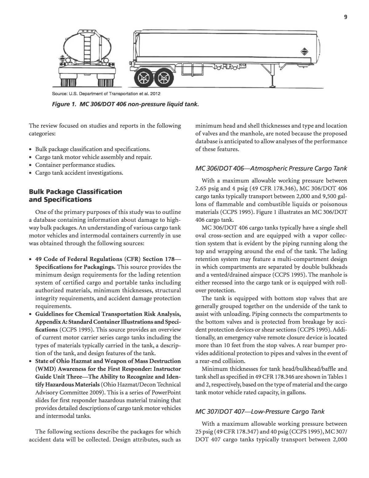
9 The review focused on studies and reports in the following categories: ⢠Bulk package classification and specifications. ⢠Cargo tank motor vehicle assembly and repair. ⢠Container performance studies. ⢠Cargo tank accident investigations. Bulk Package Classification and Specifications One of the primary purposes of this study was to outline a database containing information about damage to high- way bulk packages. An understanding of various cargo tank motor vehicles and intermodal containers currently in use was obtained through the following sources: ⢠49 Code of Federal Regulations (CFR) Section 178â Specifications for Packagings. This source provides the minimum design requirements for the lading retention system of certified cargo and portable tanks including authorized materials, minimum thicknesses, structural integrity requirements, and accident damage protection requirements. ⢠Guidelines for Chemical Transportation Risk Analysis, Appendix A: Standard Container Illustrations and Speci- fications (CCPS 1995). This source provides an overview of current motor carrier series cargo tanks including the types of materials typically carried in the tank, a descrip- tion of the tank, and design features of the tank. ⢠State of Ohio Hazmat and Weapon of Mass Destruction (WMD) Awareness for the First Responder: Instructor Guide Unit ThreeâThe Ability to Recognize and Iden- tify Hazardous Materials (Ohio Hazmat/Decon Technical Advisory Committee 2009). This is a series of PowerPoint slides for first responder hazardous material training that provides detailed descriptions of cargo tank motor vehicles and intermodal tanks. The following sections describe the packages for which accident data will be collected. Design attributes, such as minimum head and shell thicknesses and type and location of valves and the manhole, are noted because the proposed database is anticipated to allow analyses of the performance of these features. MC 306/DOT 406âAtmospheric Pressure Cargo Tank With a maximum allowable working pressure between 2.65 psig and 4 psig (49 CFR 178.346), MC 306/DOT 406 cargo tanks typically transport between 2,000 and 9,500 gal- lons of flammable and combustible liquids or poisonous materials (CCPS 1995). Figure 1 illustrates an MC 306/DOT 406 cargo tank. MC 306/DOT 406 cargo tanks typically have a single shell oval cross-section and are equipped with a vapor collec- tion system that is evident by the piping running along the top and wrapping around the end of the tank. The lading retention system may feature a multi-compartment design in which compartments are separated by double bulkheads and a vented/drained airspace (CCPS 1995). The manhole is either recessed into the cargo tank or is equipped with roll- over protection. The tank is equipped with bottom stop valves that are generally grouped together on the underside of the tank to assist with unloading. Piping connects the compartments to the bottom valves and is protected from breakage by acci- dent protection devices or shear sections (CCPS 1995). Addi- tionally, an emergency valve remote closure device is located more than 10 feet from the stop valves. A rear bumper pro- vides additional protection to pipes and valves in the event of a rear-end collision. Minimum thicknesses for tank head/bulkhead/baffle and tank shell as specified in 49 CFR 178.346 are shown in Tables 1 and 2, respectively, based on the type of material and the cargo tank motor vehicle rated capacity, in gallons. MC 307/DOT 407âLow-Pressure Cargo Tank With a maximum allowable working pressure between 25 psig (49 CFR 178.347) and 40 psig (CCPS 1995), MC 307/ DOT 407 cargo tanks typically transport between 2,000 Source: U.S. Department of Transportation et al. 2012 Figure 1. MC 306/DOT 406 non-pressure liquid tank.
10 and 8,000 gallons of flammable liquids and mild corrosives with vapor pressures not more than 40 psi at 70°F. Figure 2 illustrates an MC 307/DOT 407 cargo tank. MC 307/DOT 407 low-pressure cargo tanks are typically made of steel with a double shell and may be lined. The lading retention system may have a multi-compartment design in which compartments are separated by double bulkheads and a vented/drained airspace (CCPS 1995). The manhole, which can withstand an internal fluid pressure of at least 40 psi, is either recessed into the cargo tank or is provided with roll- over protection. Additionally, stiffening rings add structural strength to the tank. The tank is equipped with bottom stop valves that are gen- erally grouped together on the underside of the tank to assist with unloading. Piping connects the compartments to the bottom valves and is protected from breakage by accident protection devices or shear sections (CCPS 1995). Addition- ally, an emergency valve remote closure device is located more than 10 feet from the stop valves. Minimum thicknesses for tank heads/bulkhead/baffles and tank shell as specified in 49 CFR 178.347 are shown in Tables 3 and 4, respectively, based on the type of material and the cargo tank motor vehicle rated capacity, in gallons. MC 312/DOT 412 Corrosive Cargo Tank MC 312/DOT 412 cargo tanks are characterized by a narrow cylindrical shape and are typically lined with a homogeneous corrosive resistant material to transport high density liquids and corrosives such as acetyl chloride and hydrochloric acid (CCPS 1995). The cargo tanks have a multi-compartment design; are usually constructed of steel, stainless steel, or Volume Capacity (gallons per inch of length) Minimum Head Thickness (inches) Mild Steel High Strength Low Alloy Steel & Austenitic Stainless Steel Aluminum 14 or less 0.100 0.100 0.160 Over 14 to 23 0.115 0.115 0.173 Over 23 0.129 0.129 0.187 Table 1. Specified minimum head thickness of MC 306/DOT 406 cargo tank (or bulkhead and baffle when used as tank reinforcement). Cargo Tank Motor Vehicle Rated Capacity (gallons) Minimum Shell Thickness (inches) Mild Steel High Strength Low Alloy Steel & Austenitic Stainless Steel Aluminum More than 0 to at least 4,500 0.100 0.100 0.151 More than 4,500 to at least 8,000 0.115 0.100 0.160 More than 8,000 to at least 14,000 0.129 0.129 0.173 More than 14,000 0.143 0.143 0.187 Table 2. Specified minimum shell thickness of MC 306/DOT 406 cargo tank. Source: U.S. Department of Transportation et al. 2012. Figure 2. MC 307/DOT 407 low-pressure chemical tank.
11 aluminum; and are equipped with rollover protection and splashguards that also provide rollover protection. Figure 3 illustrates an MC 312/DOT 412 cargo tank. The manhole is located at either the center or the rear of the tank. The loading area is typically covered with corro- sive resistant material; piping, hoses, and connections may be made of non-metallic materials to resist corrosion as well (49 CFR 178.348). These cargo tanks are typically equipped with the ability to be unloaded from the top using air pressure and are provided with valves both at the discharge point and inside the tank to prevent siphoning in the event of a valve failure (CCPS 1995). Discharge piping is shown in Figure 3 at the rear of the tank. Minimum thicknesses for tank head/bulkhead/baffle and tank shell as specified in 49 CFR 178.347 are shown in Tables 5 and 6, respectively, based on the type of material, the cargo tank motor vehicle rated capacity, in gallons, and the lading density at 60°F. MC 331 High-Pressure Gas Cargo Tank MC 331 cargo tanks are typically used to transport lique- fied pressurized gases (49 CFR 178.337). With a maximum allowable working pressure between 100 and 500 psig, MC 331 cargo tanks are made of steel or aluminum using seam- less or welded construction. Aluminum tanks are insulated Volume Capacity (gallons per inch of length) Minimum Head Thickness (inches) Mild Steel High Strength Low Alloy Steel Austenitic Stainless Steel Aluminum 10 or less 0.100 0.100 0.100 0.160 Over 10 to 14 0.100 0.100 0.100 0.160 Over 14 to 18 0.115 0.115 0.115 0.173 Over 18 to 22 0.129 0.129 0.129 0.187 Over 22 to 26 0.129 0.129 0.129 0.194 Over 26 to 30 0.143 0.143 0.143 0.216 Over 30 0.156 0.156 0.156 0.237 Table 3. Specified minimum head thickness of MC 307/DOT 407 cargo tank (or bulkhead and baffle when used as tank reinforcement). Volume Capacity (gallons per inch of length) Minimum Shell Thickness (inches) Mild Steel High Strength Low Alloy Steel Austenitic Stainless Steel Aluminum 10 or less 0.100 0.100 0.100 0.151 Over 10 to 14 0.100 0.100 0.100 0.151 Over 14 to 18 0.115 0.115 0.115 0.160 Over 18 to 22 0.129 0.129 0.129 0.173 Over 22 to 26 0.129 0.129 0.129 0.194 Over 26 to 30 0.143 0.143 0.143 0.216 Over 30 0.156 0.156 0.156 0.237 Table 4. Specified minimum shell thickness of MC 307/DOT 407 cargo tank. Source: U.S. Department of Transportation et al. 2012 Figure 3. MC 312/DOT 412 corrosive cargo tank.
12 Volume Capacity (gallons per inch) Lading Density (pound per gallon at 60°F) Minimum Head Thickness (inches) Steel Aluminum 10 or less 10 lb and less 0.100 0.144 Over 10 to 13 lb 0.129 0.187 Over 13 to 16 lb 0.157 0.227 Over 16 lb 0.187 0.270 Over 10 to 14 10 lb and less 0.129 0.187 Over 10 to 13 lb 0.157 0.227 Over 13 to 16 lb 0.187 0.270 Over 16 lb 0.250 0.360 Over 14 to 18 10 lb and less 0.157 0.227 Over 10 to 13 lb 0.250 0.360 Over 13 to 16 lb 0.250 0.360 Over 18 10 lb and less 0.157 0.227 Over 10 to 13 lb 0.250 0.360 Over 13 to 16 lb 0.312 0.450 Table 5. Specified minimum head thickness of MC 312/DOT 412 cargo tank (or bulkhead and baffle when used as tank reinforcement). Volume Capacity (gallons per inch) Lading Density (pounds per gallon at 60°F) Distances Between Heads (and bulkheads, baffles, and ring stiffeners when used as tank reinforcement) Minimum Shell Thickness (inches) Steel Aluminum 10 or less 10 lb and less 60 in. or less 0.100 0.144 Over 10 to 13 lb 60 in. or less 0.129 0.187 Over 13 to 16 lb 60 in. or less 0.157 0.227 Over 16 lb 60 in. or less 0.187 0.270 Over 10 to 14 10 lb and less 54 in. or less 0.100 0.144 Over 54 in. to 60 in. 0.129 0.187 Over 10 to 13 lb 54 in. or less 0.129 0.187 Over 54 in. to 60 in. 0.157 0.227 Over 13 to 16 lb 54 in. or less 0.157 0.227 Over 54 in. to 60 in. 0.187 0.270 Over 16 lb 54 in. or less 0.187 0.270 Over 54 in. to 60 in. 0.250 0.360 Over 14 to 18 10 lb and less 36 in. or less 0.100 0.144 Over 36 in. to 54 in. 0.129 0.187 Over 54 in. to 60 in. 0.157 0.227 Over 10 to 13 lb 36 in. or less 0.129 0.187 Over 36 in. to 54 in. 0.157 0.227 Over 54 in. to 60 in. 0.250 0.360 Over 13 to 16 lb 36 in. or less 0.157 0.227 Over 36 in. to 54 in. 0.187 0.270 Over 54 in. to 60 in. 0.250 0.360 Over 18 10 lb and less 36 in. or less 0.129 0.187 Over 36 in. to 54 in. 0.157 0.157 Over 54 in. to 60 in. 0.187 0.270 Over 10 to 13 lb 36 in. or less 0.157 0.227 Over 36 in. to 54 in. 0.250 0.360 Over 54 in. to 60 in. 0.250 0.360 Over 13 to 16 lb 36 in. or less 0.187 0.270 Over 36 in. to 54 in. 0.250 0.360 Over 54 in. to 60 in. 0.312 0.450 Table 6. Specified minimum shell thickness of MC 312/DOT 412 cargo tank.
13 and covered with a steel jacket while steel tanks need to be insulated and covered with a steel jacket only when carry- ing a flammable gas. Insulation must be non-combustible if used for tanks carrying nitrous oxide refrigerated liquid and must be corkboard, polyurethane foam, or ceramic fiber/ fiberglass if used for tanks carrying chlorine. If the cargo tank is not insulated, it is painted white, aluminum, or a similar reflecting color on the upper two-thirds of the container. Struc- tural members, the suspension sub-frame, accident protec- tion structures, and external circumferential reinforcement devices are typically used for attachment of appurtenances and other accessories. Figure 4 illustrates an MC 331 cargo tank with vents located on top of the cargo tank and a man- hole located on the rear head. Non-chlorine cargo tank openings include gauging devices, thermometer wells, pressure relief valves, manhole openings, product inlet openings, product discharge openings, and other openings that have been closed with a plug, cap, or bolted flange. Backflow check valves or internal self-closing stop valves are located inside the cargo tank or inside a welded nozzle that is an integral part of the cargo tank. Additionally, non-chlorine cargo tanks have remote closure valves in at least two diago- nally opposite locations (CCPS 1995). Chlorine cargo tanks have only one opening on the top of the tank, which is fitted with a nozzle, an internal excess flow valve, and an external stop valve, and protected by either a manway cover or a dome cover plate (49 CFR 178.337). The minimum thickness for MC 331 tanks is based on the structural requirements of the tank and 25% of the ten- sile strength of the material used. Sulfur dioxide and chlo- rine tanks are made of steel and designed to incorporate a corrosion allowance of the lesser of an additional 20% or an additional 0.100 inches. Chlorine tanks are required to be at least 0.625 inches, including the corrosion allowance. All other MC 331 steel tanks should exceed 0.187 inches, and MC 331 aluminum tanks should exceed 0.270 inches (49 CFR 178.337). MC 338 Cryogenic Liquid Cargo Tank MC 338 cargo tanks are designed to prevent heat transfer to the lading and consist of an inner tank enclosed within an outer tank. This provides a thermos-bottle-type design where the interstitial space can be evacuated of air (vacuum). Addi- tionally, an insulation material may be provided between the inner and outer tanks. Depending on the insulation provided, each tank is rated for a specific holding time before the tank pressure exceeds the set pressure of a pressure relief valve. The insulation must also meet certain fire rating standards based upon the type of lading for which the tank was designed (49 CFR 178.338). Figure 5 illustrates an MC 338 cryogenic liquid cargo tank. The manhole, typically located on the top or rear of the tank, must be provided with a means of entrance and exit through Source: U.S. Department of Transportation et al. 2012 Figure 4. MC 331 high-pressure gas cargo tank. Source: U.S. Department of Transportation et al. 2012 Figure 5. MC 338 cryogenic liquid cargo tank.
14 Compressed Gas Tube Trailer Tube trailers transport bulk non-liquefied compressed gases such as helium, hydrogen, nitrogen, and oxygen at pressures ranging between 3,000 and 5,000 psi. A group of cylinders, meeting standards outlined in 49 CFR 178.35 are stacked and banded together in a modular or nested shape. Each cylinder is constructed using a material without seams, cracks or laminations, or other defects. Figure 6 illustrates an example configuration of cylinders in a tube trailer, and Table 8 displays some properties associated with cylinders used for tube trailers. Non-Pressurized UN Portable Tank Non-pressurized UN portable tanks are used to transport liquid and solid hazardous materials. These tanks are designed to withstand temperatures between -40°C and 50°C (-40°F and 122°F) or greater than the maximum temperature of its lading. Tanks are generally made out of steel; however, some shells may be constructed using aluminum. Additionally, tanks may be lined with a homogeneous corrosion-resistant material that is compatible with the lading. Minimum thick- the jacket, or the jacket must be marked to indicate the man- way location on the tank. Tanks designed for flammable lad- ings have a discharge opening located at the bottom centerline of the tank and are equipped with a closure that is leak tight at the tankâs maximum allowable working pressure. Accident damage protection for all valves, fittings, pres- sure relief devices, and other accessories is typically provided through a collision-resistant housing located at the rear of the tank. Additionally, pressure relief devices are protected so that they are not obstructed in the event of a collision. MC 338 cargo tanks typically have a remote means of automatic closure located at the end of the cargo tank that is furthest from the loading/unloading connection area. The tank is typically constructed of steel alloys suited for the low-temperature environment to which the tank is subjected. The minimum thickness of the steel tank is 0.187 inches or 0.110 inches if the tank is vacuum insulated or double walled with a load-bearing jacket carrying a proportionate amount of structural loads. The minimum thickness for an aluminum tank is 0.270 inches. The minimum thickness requirements for the jacket are shown in Table 7. Type Metal Jacket Evacuated Jacket Not Evacuated Gauge Inches Gauge Inches Stainless steel 18 0.0428 22 0.0269 Low carbon mild steel 12 0.0946 14 0.0677 Aluminum â = not applicable â 0.1250 â 0.1000 Table 7. Specified minimum jacket thickness of MC 338 cargo tank. Source: U.S. Department of Transportation et al. 2012 Figure 6. Compressed gas tube trailer.
15 pressure relief device continues to function in the event of a collision. Stop valves, or other suitable means of closure, are located close to the shell at all openings except for open- ings leading to venting or pressure relief devices. If the tank is insulated, a spill collection reservoir with suitable drains will surround top fittings. Bottom fittings, if provided, shall have either two or three independent shut-off valves located both close to the shell and at the end of the discharge pipe (49 CFR 178.275). nesses are specified based on the type of material used as well as the tank diameter and are exclusive of corrosion allowance. Table 9 shows the required minimum thicknesses of non- pressurized UN portable tanks as specified in 49 CFR 178.275. All UN portable tanks (see Figure 7) are constructed with supports that provide a secure base during transportation. Longitudinal bars may be used to provide additional lateral support. Reinforcement rings or bars fixed across the frame, an ISO frame, or an insulation jacket may be used to provide additional protection against overturning. A bumper or rear frame may also be equipped to protect against rear impacts (49 CFR 178.275). A pressure relief device is located within the vapor space on top of the shell, near the longitudinal and transverse cen- ter. Accident damage protection is provided to ensure the Cylinder Type Max. Water Capacity (lb) Cylinder Dimensions (where max. water capacity is not provided) Min. Service Pressure (psig) Max. Service Pressure (psig) Material Type Max. Diameter (inches) Max. Length (feet) 3A 1,000 N/S N/S 150 N/S Open-Hearth or Electric Steel 3AX 1,000 N/S N/S 500 N/S Open-Hearth or Electric Steel 3AA 1,000 N/S N/S 150 N/S Open-Hearth, Basic Oxygen, or Electric Steel 3AAX 1,000 N/S N/S 500 N/S Open-Hearth, Basic Oxygen, or Electric Steel 3B 1,000 N/S N/S 150 500 Open-Hearth or Electric Steel 3BN 125 N/S N/S 150 500 Nickel 3E N/S 2 2 N/S 1,800 Open-Hearth or Electric Steel 3HT 150 N/S N/S 900 N/S Open-Hearth or Electric Furnace Steel 3T 1,000 N/S N/S 1,800 N/S Open-Hearth, Basic Oxygen, or Electric Furnace Steel 3AL 1,000 N/S N/S 150 N/S Aluminum Note: N/S = Not Specified Table 8. Specified seamless cylinder properties. Source: U.S. Department of Transportation et al. 2012 Figure 7. Portable tank. Tank Diameter Minimum Thickness [mm (in)] Reference Steel Absolute Up to 1.8 meters 5 (0.197) 3 (0.100) 1.8 meters and above 6 (0.200) 3 (0.100) Table 9. Specified minimum thicknesses for non-pressurized UN portable tanks.
16 scenario. To understand this aspect further, information was obtained from the FMCSA report entitled Guidelines for the Operation, Assembly, Repair, Testing, and Inspection of Hazard- ous Material Cargo Tanks (Bowman et al. 2009). The report identifies factors that affect the service life of a cargo tank based on industry comments, regulatory documents, and profes- sional organizationsâ guidance. The report also provides rec- ommendations to minimize the effects of those factors, thus extending the service life of a cargo tank. Industry input was gathered through direct observation, interviews, and focus groups. These focus groups consisted of 63 administrators and maintenance/inspection personnel from (1) commercial fleets carrying hazardous materials and (2) certified inspection/ repair facilities. Industry comments were then supplemented with recommended procedures from industry-related associa- tions and engineering societies, resulting in a list of industry- recommended practices. The following sections discuss the report in more detail and provide further information on cargo tank motor vehicle assembly and repair. Cargo Tank Assembly The following three types of frames to which cargo tanks may be mounted are identified by Bowman et al. (2009): ⢠A full-sized semi-trailer frame. ⢠A front, fifth-wheel mounting frame and a rear wheel mount- ing frame or bogie (used when the cargo tank serves as the load-bearing structure). ⢠A straight truck chassis or âbobtailâ (used when the cargo tank serves as the load-bearing structure). Bowman et al. (2009) recommend that the following attach- ments be examined for material compatibility in order to avoid galvanic corrosion: ⢠Supports designed to prevent excessive localized stresses. ⢠Round, oval, or rectangular reinforcing plates used between a support or the chassis and the tank. ⢠Saddles extending over at least one-third of the circum- ference. ⢠Stiffening rings. ⢠Longitudinal stringers at the top of the tank. ⢠Gussets. Bowman et al. (2009) also provide a review of the instal- lation guidelines for manhole assemblies, accident damage protection, pressure relief valves, tank outlets, and gauges for DOT 406/407 and 412 specification cargo tanks and for MC 330 and MC 331 specification cargo tanks. Information is also provided concerning emergency discharge control equip- ment, engine fuel lines, liquid level gauging devices, pumps and compressors, and the installation of linings and coatings. Pressurized UN Portable Tank Pressurized UN portable tanks are used to transport non-refrigerated liquefied gases. Tanks have a circular cross- section and are made of steel with a minimum thickness of 4 millimeters (0.2 inches). If insulated, the insulation either covers between the upper third and upper half of the shell surface or completely covers the shell and is separated from the shell by an air space. Like all UN portable tanks, the tank is constructed with supports that provide a secure base dur- ing transportation. Longitudinal bars may be used to provide additional lateral support. Reinforcement rings or bars fixed across the frame, an ISO frame, or an insulation jacket may be used to provide additional protection against overturning. A bumper or rear frame may also be provided to protect against rear impacts (49 CFR 178.276). A pressure relief device is located within the vapor space on top of the shell, near the longitudinal and transverse center. Accident damage protection is provided to ensure the pressure relief device continues to function in the event of a collision. All other openings greater than 1.5 millimeters (0.100 inches) have at least three mutually independent shut-off devices in series. Types of shut-off devices can include stop valves, excess flow valves, integral excess flow valves, external stop valves, blank flanges, thread caps, and plugs (49 CFR 178.276). Cryogenic UN Portable Tank Cryogenic UN portable tanks are used to transport refrig- erated liquefied gases. The tank is constructed of steel and designed to hold at least 450 liters (118.9 gallons). Consisting of an inner shell enclosed in a jacket, the tank is insulated by either an intermediate layer of solid, thermally insulating material or by vacuum (49 CFR 178.277). Like all UN portable tanks, the tank is constructed with supports that provide a secure base during transportation. Longitudinal bars may be used to provide additional lateral support. Reinforcement rings or bars fixed across the frame, an ISO frame, or an insulation jacket may be used to provide additional protection against overturning. A bumper or rear frame may also be provided to protect against rear impacts. All filling and discharge openings have at least two mutually independent stop valves and one blank flange or equivalent device in series. Two independent reclosing pressure relief devices are provided for every shell. Pressure relief devices are designed to resist dynamic forces and to open automati- cally when pressures exceed the maximum allowable working pressure by 10% (49 CFR 178.277). Cargo Tank Motor Vehicle Assembly and Repair Besides container design specifications, industry practices may influence the performance of cargo tanks in an accident
17 tors involved in the certification of repairs to cargo tanks. Indi- viduals with National Board Inspection Code certification are ideal candidates for providing information as to the location and extent of damage sustained by the lading retention system of vehicles involved in accidents. Container Performance Studies Container performance studies were reviewed to determine how existing crash data have been used in past studies. For highway cargo tanks, a number of analyses have been per- formed to evaluate the performance of front heads and con- tainer performance in rollover scenarios. Key factors required to perform similar statistical analyses of container perfor- mance are identified. In Safety Performance of Tank Cars in Accidents: Probabilities of Lading Loss (Treichel et al. 2006), the safety performance of tank cars in accidents is analyzed using multivariate logis- tic regression to examine the probability of lading loss from railway tank cars involved in accidents. The underlying data- base, the RSI-AAR TCAD, is the result of long-term industry effort to record detailed tank car accident damage informa- tion. Treichel et al. (2006) determined which cars should be included in their analysis by detailing inclusion criteria that would ensure that the probability estimates developed would be relevant and resulting container performance comparisons meaningful. The variables considered in the regression analy- sis include pressure car versus non-pressure car, head thick- ness, head shield type, shell thickness, presence of a jacket, presence of shelf couplers, presence of bottom fittings, pres- ence of bottom fitting protection, and location of accident (yard versus mainline). Variables were evaluated to determine whether they had a significant effect on the probability of lad- ing loss, and a coefficient was developed for each significant factor. Using these coefficients, regression equations to calcu- late the conditional probability of release were determined for specific tank car components, namely the head, shell, and top and bottom fittings. Improving Crashworthiness of Front Heads of MC-331 Cargo Tank Motor Vehicles (Selz and Heberling 2000) evaluates design alternatives to improve MC 331 cargo tank head crashworthi- ness. Selz and Heberling (2000) used drop tests to develop a computer model capable of predicting deformations and rup- ture of a cargo tank. The model was refined using data from an accident that occurred in White Plains, New York, in 1994. Two additional accidents were selected for similar analysis; however, the accident reports lacked sufficient data. Elements of the accident report that were required to develop an ana- lytical correlation included the following: ⢠Speed of the trailer. ⢠Characteristics of the object struck (i.e., shear capacity and weight of portion sheared). Cargo Tank Repair Bowman et al. (2009) provide recommended practices for the repair of cargo tanks based on existing regulations, codes, and standards. The report also provides recommendations for the following conditions requiring repair: ⢠Corrosion. It is recommended that operators be aware of corrosion and that a corrosion mitigation plan be devel- oped that establishes the process for determining the type of corrosion and the proper repair procedures needed for that type. If the wall thickness has not been compromised, pitting corrosion, line corrosion, and general corrosion can be repaired using a weld overlay. Otherwise, the repair will consist of a flush patch. Galvanic corrosion is miti- gated by eliminating the cause or by removing the incom- patible material. Other types of corrosion include erosion/ corrosion, crevice corrosion, and passivation. ⢠Weld defects. It is recommended that welding quality con- trol policies and procedures be established that not only ensure that consistent welding techniques are used by all company personnel but also identify all weld defects and the procedures for rectifying such defects before placing cargo tanks back into service. Weld cracking, undercut- ting, excessive reinforcement, insufficient reinforcement, and incomplete fusion are some examples of weld defects. ⢠Cargo tank distortion. Flush patch repair is required if dents with a weld exceed 0.5 inches or if dents without a weld exceed 1 inch or a depth greater than one-tenth of the greatest dimension of the dent. Gouges may be repaired by blending and re-evaluated for service. ⢠Cracking. It is recommended that policies for identifying and correcting material cracking be established. Recom- mended policies should include properly trained per- sonnel and proper procedures. Types of cracking include fatigue cracks, structural overload, non-ductile fracture, stress-corrosion cracking, transgranular stress, and hydro- gen embrittlement. ⢠Bulkhead and baffle defects. It is recommended that bulk- heads and baffles be attached and joined appropriately to ensure structural integrity. Bowman et al. (2009) indicate that there are two forms of construction: fillet welding the flange of the baffle to the shell and welding the edge of the baffle without a flange directly to the shell. Using flanged construction is more desirable. ⢠Omitted or undersized welding pads. It is recommended welding pads be used appropriately to prevent cargo tank shell defects. Bowman et al. (2009) indicate that omitting or using undersized pads is a major contributor to defects in attachment of shell to frame, rollover-protection devices, or rear-end structures. Bowman et al. (2009) anticipated the current regulation that requires National Board certification of facilities and inspec-
18 ⢠Driver factors including driver age, vehicle speed, and driver errors or distractions. The analysis resulted in some unexpected findings. Namely, the majority of truck rollover crashes involved a single vehi- cle in dry pavement conditions and were due to driver error. Speeding, presence of an interchange, and truck configura- tion had little significance on causality. Pape et al. (2007) rec- ommended the use of driving simulators to train drivers on how to avoid pre-rollover events, electronic stability aids to ensure proper speeds on curves, lower center of gravity vehi- cle designs, and proper signage where unusual curves, grades, or traffic patterns exist. In The Dynamics of Tank-Vehicle Rollover and the Implications for Rollover-Protection Devices (Winkler et al. 1998), two tank truck and five combination vehicle (tractor and semi-trailer) rollover computer simulations are developed. The simulations were intended to calculate the range of initial conditions of input for three scenarios: ⢠The vehicle falls on its side and engages the rollover- protection devices. ⢠The vehicle becomes airborne and the rollover-protection devices directly impact the ground at a speed of 6 to 18 feet per second and up to 30 feet per second in severe cases. ⢠The vehicle lands on its side and slides into a vertical barrier oriented parallel to the roadway. In particular, the following maneuvers were tested: ⢠Intersection turn where the vehicle attempts to follow a 100-foot radius curve at speeds ranging between 20 and 55 miles per hour. ⢠Highway/exit ramp turn where the vehicle attempts to follow a 500-foot radius curve at speeds between 50 and 70 miles per hour. ⢠Curb-strike maneuver where the vehicle strikes a 6-inch curb while attempting to travel in a 500-foot radius curve between 35 and 55 miles per hour. Various angles of impact between 5 and 30 degrees were tested. ⢠Guardrail-strike maneuver similar to curb-strike but occurring when a vehicle strikes a guardrail 16 to 36 inches above the ground. ⢠Spiral turn where the steering wheel angle is increased at a rate of 2 degrees per second while traveling at 40 miles per hour. ⢠High-speed avoidance maneuver where the vehicle, trav- eling at 50 miles per hour, turns slightly to the right and severely overcorrects left. ⢠Step-turns where the steering wheel is âcrankedâ to a pre- determined angle while traveling at speeds between 30 and 70 miles per hour. ⢠Combined weight of the vehicle and cargo. ⢠Response of the cargo tank to the crash (i.e., amount of deformation and size of rupture). The model enabled prediction of the interaction of steel, propane, foam, and roadway structures in a crash scenario. Several possible head configurations were tested including bare head design, incorporation of a secondary head, and incorporation of energy-absorbing material between two heads. The model indicated that the bare head design would not be able to withstand an impact above 30 miles per hour. The secondary head increased the crashworthiness of the tank except in the most severe crash scenarios. The addition of energy-absorbing material (foam) between the primary and secondary heads further improved the crashworthiness of the container. The critical velocity of a train part striking the head of a European liquefied petroleum gas (LPG) railway tank car is calculated in LPG Rail Tank Cars Under Head-On Colli- sions (Lupker 1990). The analysis used scaled models and finite difference calculations to show that non-symmetrical deformation begins to occur when the deformation is one order of magnitude greater than the shell thickness. The analytical approach used indicated that indentations greater than 30 times the shell thickness would result in penetration of the tank car. Cargo Tank Roll Stability Study (Pape et al. 2007) features an analysis of the factors causing cargo tank rollover events through a review of 966 rollover accident records from the MCMIS, 89 cargo tank accident records from the Large Truck Crash Causation Study (LTCCS), 1,837 cargo tank accident records from the TIFA database, and 197 rollover crashes from the GES databases. Using the information obtained from these databases, the following four complementary approaches to reducing the incidence of cargo tank rollovers were evaluated: ⢠Improved driver training. ⢠Electronic stability aids. ⢠Modified vehicle designs to increase vehicle stability. ⢠Modified highway design. The following factors were identified in various databases as providing a contributing cause to rollover events: ⢠Crosscutting factors including the primary reason or critical event and the pre-crash event or maneuver. ⢠Vehicle factors including the body type, hazardous material involvement, load, mechanical problems, and cargo tank specification. ⢠Roadway and environment factors including road type, population area, roadway surface condition, roadway cur- vature, and location relative to an interchange.
19 Cargo Tank Accident Investigations Accident investigations were also reviewed to identify key factors for inclusion in a database enabling statistical analy- ses of container performance. The following sources repre- sent serious, relatively unique accidents that could have been avoided. Similar accidents should be easily identified by the proposed database. In Safety Advisory: Chlorine Transfer Hose Failure (U.S. Chemical Safety and Hazard Investigation Board 2002) an incident occurring on August 14, 2002, in which a chlorine railcar transfer hose ruptured catastrophically and released 48,000 pounds of chlorine into nearby areas was reviewed. The U.S. Chemical Safety and Hazard Investigation Board determined that the hose was made of an incorrect material and issued a Safety Advisory recommending that chlorine handlers using non-metallic-lined chlorine transfer hoses ensure that these hoses are constructed with the appropri- ate structural braiding layer. âCollision of Cargo Tank Truck and Automobile and Sub- sequent Fire, Upper Pittsgrove Township, New Jersey, July 1, 2009,â an NTSB Hazardous Materials Accident Brief (2009), documented the investigation of the collision of an MC 306 cargo tank semi-trailer and an automobile in which the auto- mobile became wedged beneath the cargo tank truck and was dragged about 500 feet. As a result of the crash, load- ing line four was ruptured. Because the cargo tankâs load- ing lines contained gasoline, about 13 gallons were released and ignited. Similar accidents had occurred in Yonkers, New York, on October 9, 1997, and in Wilmington, Delaware, on February 15, 1998. The NTSB recommended that carrying of hazardous materials in cargo tank external piping should be prohibited. Another Hazardous Materials Accident Brief, âRelease of Hazardous Materials from Cargo Tank, Middletown, Ohio, August 22, 2003â (NTSB 2004), documented the inves- tigation of an MC 331 cargo tank in which the front head cracked open while the cargo tank was being loaded, releas- ing anhydrous ammonia, a poisonous and corrosive gas. The cargo tank head had a 16-inch-long, through-wall crack next to the radial weld as well as two other cracks that did not lead to lading loss. The cracks formed as a result of stress- corrosion cracking occurring when carbon steel, in the pres- ence of a caustic material, is exposed to tensile stresses. It is recommended that anhydrous ammonia containing less than 0.2 percent water by weight should not be loaded into cargo tanks manufactured of quenched and tempered steel (marked QT). In the Hazardous Materials Accident Brief titled âCata- strophic Structural Failure of MC-307 Cargo Tank, South Charleston, WV, January 5, 2002â (NTSB 2003), the investi- gation of a catastrophic structural failure between the front and center tanks of an MC 307 cargo tank consisting of The simulations identified several dynamic parameters present in rollover scenarios including roll, pitch, and yaw attitude upon ground strike and vertical, lateral, and roll impact velocity. The computer simulation indicated that a load 400 times the weight of the vehicle results from an input velocity of 24 feet per second (16.4 miles per hour) striking the ground at an angle between 10 and 15 degrees and having a crush allowance of 1 foot. As the impact force results in high- profile, bulky rollover-protection measures, the authors indicate that tank designs allowing more tank deformation may be desirable. Winkler et al. (1998) provided two alter- natives to achieving increased deformation: increasing the allowable deformation of the tank (i.e., when the strength of protective devices exceeds the strength of the tank) or increasing the allowable deformation of the accident pro- tection devices. In all designs, the focus should be on energy dissipation that is ideally achieved through a constant crush force. Existing and modified rollover-protection devices, such as various staple designs or flat rail designs with a vari- ety of dams, were analyzed. Results indicated that designs such as staple designs typically result in higher crush forces and are less able to support these forces because of their geometry. In Full-Scale Rollover Testing of Commercial Cargo-Tank Vehicles (Winkler 2009), single unit cargo tank trucks and combination cargo tank vehicles (tractor-semi-tanker) were analyzed to determine crashworthiness of the cargo tank and verify the results of a previous simulation study (Winkler et al. 1998). The purpose of the experiment was to determine the attitude and velocities at the moment of impact rather than the amount of damage sustained by the lading retention system. Since the single unit vehicle was being tested multiple times in progressively more severe maneuvers, the cab was equipped with close-fitting roll bars. On the other hand, no additional rollover protection was used on the combination vehicle as it was only being tested once in a very severe maneuver. Total mass and static rollover threshold were determined for both vehicles. Initial vehicle speeds of the single unit vehicle prior to the critical movement ranged from 49.9 kilometers per hour (31 miles per hour) to 80.6 kilometers per hour (50.1 miles per hour) for all tests resulting in a rollover. The combination vehicle was tested at 73.4 kilometers per hour (45.6 miles per hour) and, as is typical of rollover maneuvers, the trailer rolled prior to the tractor cab. Winkler (2009) attributes the rolling of the trailer prior to the tractor cab to the low center of gravity and torsion-compliant design of the tractor and also indi- cates that the trailer had rolled 104 degrees by the time it struck the ground because of the narrow MC 312 profile and heavy-side tires. The amount of deformation sustained by the trailer or truck, as well as the potential for lading loss, was not reported.
20 Facility AâSingle-Stage Manufacturer Facility A is a single-stage trailer manufacturing facility in which the tank is manufactured and mounted on a truck chassis or trailer frame. Facility A produces an average of 7,000 tanks per year (over the past 30 years) of which approximately three- quarters are DOT 406 containers. For each tank produced, this facility records the following information in a regularly main- tained database: ⢠Tank identification number. ⢠Original owner. ⢠Date of manufacture. ⢠Design type. ⢠Model. ⢠Total trailer capacity. ⢠Gross axle weight. ⢠Number of axles. ⢠Number of compartments. ⢠Compartment size. ⢠Number of bulkheads. ⢠Load corresponding to compartment size. Additionally, certificates of compliance are kept on file and drawings for each model have been retained for the past 50 years. Therefore, design information is still available for most tanks manufactured by this supplier that continue to be operated. The representatives at Facility A are proponents of improv- ing the roll stability of their trailers by including a trailer- mounted roll stability control (RSC) system and mounting the tanks on a âwide-trackâ where dual wheels are spaced at 77.5 inches, as opposed to ânarrow trackâ where dual wheels are spaced at 71.5 inches. Representatives at Facility A indi- cated that these two measures are among the most influential measures for reducing rollovers; however, these measures are often difficult to implement for two reasons: ⢠Some states do not allow wide-track trailers. ⢠Insurance companies do not provide reduced premium incentives for roll stability devices; therefore, it is difficult to convince tank owners to incur the extra cost of installa- tion of these systems. Facility A representatives indicated that Form DOT F 5800.1 would be useful; however, it is their belief that the reported data are neither accurate nor complete. Furthermore, the form is not capable of identifying whether the tank itself ruptured or whether lading loss occurred solely because of non-accident causes such as closures that have not been properly secured. It was suggested that an accident damage database would benefit from the inclusion of basic information recorded on the name three independent but connected tanks was documented. The incident resulted in the closure of an intersection for 7 hours, and, although no hazardous materials were released, the total cost of damage, clean-up, and lost revenues was esti- mated to be $18,000. The catastrophic structural failure was determined to be the result of extensive corrosion. It was rec- ommended that all similar tanks be inspected for corrosion and that inspection continue to occur periodically. Industry Knowledge and Opinion A successful accident damage database requires the collec- tion of relevant information at minimal cost and with full cooperation or participation from the key industry stake- holders including package manufacturers, carriers, shippers, and repair facilities. Several companies from each stakeholder group were visited and interviewed to determine what infor- mation is currently recorded regarding bulk package design and/or accident damage. Through these stakeholder interviews, it was ascertained that, due to the large differences in bulk package use and acci- dent performance associated with different specification con- tainers, a process to engage a larger number of stakeholders was required. Therefore, a set of stakeholder surveys were devel- oped and distributed. This distribution occurred, where pos- sible, through respective stakeholder industry associations. Stakeholders who were not members or affi liates of industry associations received individual survey invitations. The following sections describe the survey process and information collected regarding the current use of accident damage protection and accident prevention measures, tank parts and appurtenances of interest, and proposed accident data fields. Site Visits The research team visited a single-stage manufacturing facil- ity (Facility A), a final-stage manufacturing and repair facility (Facility B), and a repair facility (Facility C) to achieve the following objectives: ⢠Learn about design, manufacturing, and repair processes that are unique to cargo tank trailers and cargo tank motor vehicles. ⢠Identify additional data fields that should be considered for inclusion in a possible accident damage database. Budget constraints prevented visits to facilities for ISO/UN portable tanks, as they tend to be located outside of the United States. The following subsections summarize what was learned at each site.
21 Additionally, when fatigue cracks develop in the shell, such as what might occur around support appendages, the influence of repair, maintenance, and qualification practices on the performance of cargo tanks that are later involved in crashes deserves more analysis. In addition to examining tank maintenance practices and structural integrity histories in an accident damage data- base, Facility B representatives indicated that it would be useful to include the year the trailer was manufactured as well as whether the vehicle was equipped with RSC. Facility CâRepair Facility Facility C is part of a national chain of repair facilities that primarily conduct inspections and scheduled maintenance on atmospheric pressure (MC 306 and DOT 406), low-pressure chemical (MC 307 and DOT 407), corrosive material (MC 312 and DOT 412), and liquefied high-pressure gas (MC 331) bulk packages. Of the tanks inspected at this facility, it was reported that approximately 30 percent are cracked (typically around dolly legs or the rear bulkhead) or leaking (typically in pipes that are clamped together as opposed to one-piece bent piping). Facility Câs representative indicated that even MC 331 bulk packages are susceptible to structural discrep- ancies (such as corrosion in the shell) that may make the shell less able to withstand a crash. Facility C repairs tanks that have been involved in an acci- dent approximately once a month. Accident damage is typi- cally in the form of either dents in the tank shell or piping that has sheared away from the bulk package. Facility C representatives indicated that the only informa- tion they would be interested in obtaining from a database is information regarding who had performed a previous repair. Furthermore, although inspection forms are filled out on a computer, the facility maintains only hard copies of repair information and would prefer faxing information pertaining to a possible accident damage database in the future (particu- larly if participation was voluntary). Surveys Due to the potential differences in the use of bulk pack- age accident performance data, five surveys, targeting pack- age manufacturers, carriers, shippers, repair facilities, and researchers, were developed. One of the objectives of the surveys was to gain insight on what information different stakeholders believed would be most useful in an accident damage database. Questions were tailored to draw on each survey groupâs industry expertise. Copies of the surveys, as well as an explanation of the survey questions, can be found in Appendix A. plate and specification plate affixed to each tank as well as the following information: ⢠Length of the trailer and all containers. ⢠Length and dimensions of the ruptured tank. ⢠Location of the ruptured tank (within the trailer). ⢠Shape of the tank (round or oval). ⢠Gross vehicle weight. Additionally, this facility suggested that design breakthroughs or regulatory accommodations are needed to offset the weight of damage prevention measures. Unless weight-offsetting measures are identified and implemented, the managers at Facility A concluded that additional strategies would not be voluntarily adopted because of the difficulty in simultane- ously increasing state weight limits. Facility BâFinal-Stage Manufacturing and Repair Facility Facility B is a final-stage manufacturing and repair facil- ity that focuses on the assembly, repair, and inspection of truck-mounted atmospheric and low-pressure aluminum bulk packages. Testing includes annual and 5-year inspections as well as biannual ultrasonic thickness testing at approxi- mately 160 points around the bulkhead and in areas that have high stresses (structural areas). Facility B includes top safety performance in their goals, provides expertise at the scene of hazardous materials tank truck crashes, and trains DOT officers in techniques for investigating crash sites. Facility B representatives identified two main causes of lading loss: ⢠Rollover accidents in which the structural support for the tank influences whether or not lading loss occurs. Tanks lacking an underbelly structure often twist in rollover acci- dents. When this occurs, the bulkheads are typically torn at the seams, resulting in a leak that fills the void space between bulkheads (if there are multiple compartments in a tank). The product then fills the void space and exits the tank through specification vents. ⢠Accidents involving another vehicle in which incorrectly repaired piping is compromised. Facility B representatives indicated that they have noticed piping repairs performed by other repair facilities in which a crack that initiated in the shear plane has been welded closed. The shear plane is designed to allow appurtenances such as external piping to break free so that the tank is not compromised in an acci- dent scenario. This means that welding near the shear plane may result in rupture of the bulk package if it is involved in an accident.
22 single-stage manufacturers while one was an incomplete vehi- cle manufacturer. They mostly manufactured trailer-mounted tanks although some MC 306/DOT 406 and MC 331 tanks were truck-mounted. Similarly, the majority of repair facilities repair trailer-mounted bulk packages with the exception of two facilities that repair mostly truck-mounted bulk packages. The number of survey respondents manufacturing, repair- ing, or using different bulk packages, as shown in Tables 11 through 17, show that with the exception of the manufac- ture of cryogenic liquid cargo tanks (MC 338) and compressed gas tube trailers, most types of U.S. DOT-specification bulk packages are represented to some degree by survey responses. In contrast, Table 19 shows that the portable tank industry is underrepresented by survey responses. Furthermore, survey responses convey opinions of portions of the industry work- ing with other types of tanks including non-specification tanks used for combustible materials (see Table 18), food grade pack- ages, and vacuum packages (see Table 20). Comparing Tables 11 through 20, the top three bulk packages used by the carrier sur- vey respondents are low-pressure cargo tanks (built to MC 307 or DOT 407 specifications), atmospheric pressure cargo tanks (built to MC 306 or DOT 406 specifications) and corrosive cargo tanks (built to MC 312 or DOT 412 specifications). The top three bulk packages used by the shipper survey respon- dents are low-pressure cargo tanks (built to MC 307 or DOT 407 specifications), corrosive cargo tanks (built to MC 312 or DOT 412 specifications), high-pressure gas cargo tanks (built to MC 331 specifications), and pressurized UN portable tanks. As part of the survey process, the following industry orga- nizations were asked to encourage their members to partici- pate by filling out a survey: ⢠Truck Trailer Manufacturers Association (TTMA). ⢠International Tank Container Organization (ITCO). ⢠National Tank Truck Carriers Inc. (NTTC). ⢠American Chemistry Council (ACC). ⢠American Petroleum Institute (API). ⢠Compressed Gas Association (CGA). ⢠American Trucking Associations (ATA). ⢠American Transportation Research Institute (ATRI). Response Rates The response rates for the surveys (see Table 10) were on par with response rates of previous industry surveys. Since the number of responses is considered a small sample size (less than 30), generalization of responses to a particular stakeholder group may include biases that are unable to be detected. However, by pooling survey responses together, industry preferences may be accurately portrayed. Demographics of Survey Responders Survey responders were asked several demographic ques- tions in order to be able to relate their opinions to the opinions of other stakeholder groups. Two of the manufacturers were Stakeholders Estimated Number of People Surveyed Number of Responses Received Approximate Response Rate Manufacturers 20 3 15% Repair Facilities 70 8 11% Carriers 360 29 8% Shippers 32 7 22% Researchers 38 8 21% Table 10. Survey response rates. Stakeholder Number of Stakeholder Companies % of Stakeholder Respondents Quantity of Tanks per Year Bulk Tank Manufacturers 2 67% 100â1,000 Repair Facilities 5 63% 1â199 (< 50% damaged in accidents) 1 13% 200â499 (< 25% damaged in accidents) 1 13% > 1,000 (< 25% damaged in accidents) Carriers 17 59% Shippers 2 29% A blank cell indicates that the field is not applicable. Table 11. Number of respondents working with atmospheric pressure cargo tanks (MC 306 or DOT 406).
23 Stakeholder Number of Stakeholder Companies % of Stakeholder Respondents Quantity of Tanks per Year Bulk Tank Manufacturers 2 67% 10â99 Repair Facilities 4 50% 1â199 (< 25% damaged in accidents) 1 13% 200â499 (< 25% damaged in accidents) Carriers 15 52% Shippers 5 71% A blank cell indicates that the field is not applicable. Table 13. Number of respondents working with corrosive cargo tanks (MC 312 or DOT 412). Stakeholder Number of Stakeholder Companies % of Stakeholder Respondents Quantity of Tanks per Year Bulk Tank Manufacturers 2 67% 100â1,000 Repair Facilities 4 50% 1â199 (< 25% damaged in accidents) 1 13% 500â1,000 (< 25% damaged in accidents) 1 13% > 1,000 (< 25% damaged in accidents) Carriers 23 79% Shippers 5 71% A blank cell indicates that the field is not applicable. Table 12. Number of respondents working with low-pressure cargo tanks (MC 307 or DOT 407). Stakeholder Number of Stakeholder Companies % of Stakeholder Respondents Quantity of Tanks per Year Bulk Tank Manufacturers 1 33% 10â99 Repair Facilities 4 50% 1â199 (< 25% damaged in accidents) Carriers 9 31% Shippers 5 71% A blank cell indicates that the field is not applicable. Table 14. Number of respondents working with high-pressure gas cargo tanks (MC 331). Stakeholder Number of Stakeholder Companies % of Stakeholder Respondents Quantity of Tanks per Year Bulk Tank Manufacturers 0 0% Repair Facilities 2 25% 1â199 (< 25% damaged in accidents) Carriers 3 10% Shippers 2 29% A blank cell indicates that the field is not applicable. Table 15. Number of respondents working with cryogenic liquid cargo tanks (MC 338).
24 Stakeholder Number of Stakeholder Companies % of Stakeholder Respondents Quantity of Tanks per Year Bulk Tank Manufacturers 1 33% 10â99 1 33% 100â1,000 Repair Facilities 1 13% 1â199 (< 25% damaged in accidents) 1 13% 200â499 (< 25% damaged in accidents) Carriers 3 10% Shippers 0 0% A blank cell indicates that the field is not applicable. Table 16. Number of respondents working with asphalt cargo tanks. Stakeholder Number of Stakeholder Companies % of Stakeholder Respondents Type of Portable Tank Bulk Tank Manufacturers 0 0% Repair Facilities 0 0% Carriers 1 10% Pressurized UN Portable Tank 1 10% Cryogenic UN Portable Tank Shippers 3 43% Non-Pressurized UN Portable Tank 4 57% Pressurized UN Portable Tank 2 29% Cryogenic UN Portable Tank A blank cell indicates that the field is not applicable. Table 19. Number of respondents working with portable tanks. Stakeholder Number of Stakeholder Companies % of Stakeholder Respondents Quantity of Tanks per Year Bulk Tank Manufacturers 2 67% 10â99 Repair Facilities 0 0% 1â199 (< 25% damaged in accidents) Carriers 5 17% Shippers 0 0% A blank cell indicates that the field is not applicable. Table 18. Number of respondents working with non-specification tanks for combustible materials. Stakeholder Number of Stakeholder Companies % of Stakeholder Respondents Quantity of Tanks per Year Bulk Tank Manufacturers 0 0% Repair Facilities 2 25% 1â199 Carriers 3 10% Shippers 3 43% A blank cell indicates that the field is not applicable. Table 17. Number of respondents working with compressed gas tube trailers.
25 America, while one shipper reported making between 1,000 and 9,999 shipments, and two others reported making over 50,000 shipments. The types of hazardous materials shipped by these companies represent all classes of materials. Table 21 illustrates the hazardous material classes trans- ported by 29 carriers and 7 shippers. The majority of carriers who responded to the survey transport materials classified as Class 3âflammable and/or combustible liquids (transported by 90% of respondents); Class 8âcorrosive substances (trans- ported by 83% of respondents); and Class 9âmiscellaneous hazardous materials/products, substances, or organisms (trans- ported by 72% of respondents). Chemical/petroleum carriers were also asked questions concerning the number of trips made per year. In general, there was a wide range in the reported number of bulk tank deliveries of hazardous materials made per year. Four carriers make between 100 and 999 deliveries per year, eleven make between 1,000 and 9,999 deliveries per year, five reported mak- ing between 10,000 and 50,000 deliveries per year, and nine reported making over 50,000 deliveries per year. The seven shipper respondents represented shipping operations of vari- ous sizes. The majority of shipper respondents reported that their companies made between 10,000 and 50,000 highway shipments of hazardous materials using bulk tanks in North Stakeholder Number of Stakeholder Companies % of Stakeholder Respondents Package Type Quantity of Tanks Per Year Bulk Tank Manufacturers 1 33% Food Grade Package > 1,000 1 33% Vacuum Package 100â1,000 Repair Facilities 0 0% Carriers 4 14% Other Shippers 1 14% Other A blank cell indicates that the field is not applicable. Table 20. Number of respondents working with other types of bulk packages. Hazardous Material Class Number of Carriers % of Carrier Respondents Number of Shippers % of Shipper Respondents Class 2 23 79% 5 71% Division 2.1 â Flammable gases 9 31% 3 43% Division 2.2 â Non-flammable, non- toxic gases 11 38% 4 57% Division 2.3 â Toxic gases 3 10% 3 43% Class 3 â Flammable liquids (and combustible liquids) 26 90% 4 57% Class 4 3 10% 4 57% Division 4.1 â Flammable solids 0 0% 0 0% Division 4.2 â Spontaneously combustible materials 2 7% 2 29% Division 4.3 â Water-reactive substances/dangerous when wet materials 1 3% 4 57% Class 5 13 45% 1 14% Division 5.1 â Oxidizing substances 10 34% 1 14% Division 5.2 â Organic peroxides 3 10% 1 14% Class 6 13 45% 2 29% Division 6.1 â Toxic substances 13 45% 2 29% Division 6.2 â Infectious substances 0 0% 0 0% Class 8 â Corrosive substances 24 83% 5 71% Class 9 â Miscellaneous hazardous materials/products, substances, or organisms 21 72% 3 43% Note: More than one class of material may be hauled by carriers or shipped by chemical/petroleum shippers. Table 21. Hazardous material classes transported by respondents to carrier and shipper surveys.
26 Researcher experience ranged from 3 years to 35 years, with a median of 20 years. Only one of the researcher survey respondents was employed by an organization that main- tained data regarding cargo tank accident performance mea- sures. Additionally, to relate hazardous material researchersâ responses to other stakeholder groups, researchers were asked to indicate which types of bulk tanks they are most interested in. Figure 8 illustrates the reported interests of the hazardous materials researcher groups. Types of Accident Damage Protection and Accident Prevention Measures Implemented Manufacturers, carriers, and shippers were asked questions concerning the implementation of accident damage pro- tection and accident prevention measures to gauge the types of strategies currently adopted by the industry and also to determine who might be key motivators in adopting future strategies. A summary of the survey results is provided in Table 24. From the manufacturers that replied to the survey, the incor- poration of accident damage protection measures beyond federal standards into standard tank designs is not a generally adopted practice in the bulk package manufacturing industry. There was one response for each of ânever,â âoccasionallyâ only at the request of our customers,â and âusuallyâa standard Furthermore, both carrier and shipper respondents agree that the majority of the bulk packages are owned by carriers, a sizable number of bulk packages are owned by shippers, and a few are owned by lessors (see Tables 22 and 23). Hazardous material bulk package researchers were also asked a series of demographic questions. The primary topics of the respondentsâ research included risk analysis of hazard- ous materials transportation by alternate modes (including rail and waterways), risk assessment of the safety of hazard- ous materials transportation, and bulk package performance research (including procedures to determine package integ- rity; examination of tank behavior; and manufacturing char- acteristics that affect tank integrity and the dynamic safety of tank trucks, tank design, baffles design, and anti-slosh). Related bulk package research involving the respondents included the following: ⢠All aspects of cargo tank performance. ⢠The relationship between accident environments and cargo environments or how the conveyance protects the cargo from severe accidents. ⢠The effect of infrastructure quality on accident probability. ⢠Accident likelihood. ⢠Consequences given that an accident has occurred. ⢠Rollover, stability, and control. ⢠Bulk package risk assessment. Number of Respondents Ownership Split % Carrier % Shipper % Lessor 1 100% 0% 0% 1 80%â99% 0%â19% 0% 1 60%â79% 20%â39% 0%â19% 1 60% 40% 0% 1 40% 60% 0% 1 20%â39% 60%â79% 20%â39% 1 0% 100% 0% Table 23. Bulk package ownership (as reported by shipper respondents). Number of Respondents Ownership Split % Carrier Owned % Shipper Owned % Lessor Owned 10 100% 0% 0% 11 80% â 99% 0 â 19% 0% 3 80% â 99% 0% 0 â 19% 2 60% â 79% 20% â 39% 0% 1 0% â 19% 80% â 99% 0% 1 0% â 19% 0% 80% â 99% 1 0% 0% 100% Table 22. Bulk package ownership (as reported by carrier respondents).
27 The accident prevention measures that have been incorpo- rated into standard tank design by at least one manufacturer include lowered center of gravity, electronic stability control or trailer-mounted RSC, and truck conspicuity and enhanced lighting/signaling beyond what is required by regulation. The other accident measures included in the survey (wider wheel feature on our bulk tanksâ for the following accident damage protection measures: ⢠Fitting protection beyond federal standards. ⢠Additional shell protection. ⢠Increased tank wall thickness. Figure 8. Researcher interest in specific bulk packages. Table 24. Number of companies (by stakeholder group) that have incorporated accident damage protection and prevention measures beyond federal standards. Bulk Package Manufacturers Carriers Shippers No additional measures specified 1 8 1 Accident damage protection measures Fittings protection beyond federal standards 2 8 2 Additional shell protection 2 1 0 Increased tank wall thickness 2 5 1 Other 0 2 5 Accident prevention measures Lowered center of gravity 1 10 3 Wider wheel-base 2 8 2 Electronic stability control 2 13 1 Truck-mounted RSC 2 13 2 Trailer-mounted RSC 2 12 3 Improved brakes (including disc and hybrid drum- disc brake configurations) 2 8 1 Electronic data recorders (EDRs) N/A 10 2 Tire pressure monitors 2 15 2 Automated transmissions N/A 9 1 Speed limiters N/A 21 3 Truck-specific navigation (including global positioning system [GPS] navigation aids) N/A 10 2 Truck conspicuity (devices that make the truck more visible) and enhanced lighting/signaling beyond that which is required by regulations 2 9 0
28 minimum federal requirements for bulk tanks used to trans- port hazardous materials. These additional requirements include the following accident damage protection: ⢠Fitting protection beyond federal standards. ⢠Elimination of bottom outlets for certain products. ⢠Thicker shell. ⢠Higher test pressure. In addition, several shippers reported that they require a variety of accident prevention measures. The accident pre- vention measures most often required include lowered center of gravity, trailer-mounted RSC, and speed limiters. Best Ways to Reduce Conditional Probability of Release All of the stakeholder groups were asked questions con- cerning the most effective means to improve accident damage performance of bulk packages. In addition to responding to the questions asked, several survey respondents also provided suggestions for reducing the probability of accident occur- rence. Suggested accident prevention measures and protec- tion devices are summarized in Table 25. track, advanced braking technology such as disc and hybrid drum-disk brake configurations, and tire pressure monitors) tend to only be included at the request of a customer. Of the carriers that replied to the survey, 41% indicated that they would consider additional design features offered while 28% indicated that they have a company policy that identi- fies additional requirements. The additional design features considered or specified primarily include fittings protection beyond federal standards and, to a lesser extent, increased tank wall thickness. Only one carrier identifies additional shell pro- tection as a company-specified accident damage protection measure required for the vehicles/cargo tanks used in their deliveries. A number of different accident prevention design features are incorporated into bulk packages owned by carriers (see Figure 9). However, there is no generally accepted accident prevention measure used by all carriers who specify or consider additional design features that exceed the minimum federal requirements for bulk packages used to transport hazardous materials. Furthermore, 28% of carrier survey respondents reported that they do not specify additional design features that exceed the minimum federal requirements for bulk tanks used to transport hazardous materials. The majority of shipper respondents have a company pol- icy that identifies additional design features that exceed the Figure 9. Accident prevention design features that exceed the minimum federal requirements specified or considered for carrier-owned bulk packages.
29 Identified By: Measure Bulk Package Manufacturer Repair Facility Carrier Shipper Researcher / Government For Improved Accident Protection Top-fitting protection enhancements (enlarge and increase robustness of âspill boxesâ) Improved bottom fittings protection / protective cages around any piping Remove bottom fittings Locate manual valves close to the tank Use the trailer frame to provide valve and piping protection Provide fitting securement of all closures Reduce unnecessary fittings Ensure piping, vents, piping protection, dolly legs, and rear tires do not extend beyond the profile of the tank Use a âwheels backâ trailer design to add additional protection in rear-end collisions Install under-ride protection Continuous frame rails Better dome lids Better internal valves Self-closing stop valves / Emergency valves Stronger bulkheads Increase material thickness (shell and head) Use stainless steel whenever possible Use rupture-resistant material and/or self-sealing materials Use compartmented tanks Incorporate an isolation layer Add side impact protection (perhaps designing âairbagsâ) Use U.S. DOT-specification tanks even for non-regulated materials Strap together tube tanks on trailers Proper maintenance of equipment, valves, and domes Employ an effective inspection and maintenance program Make sure load is secure and valves and manholes are properly closed and secure Maintain spill kits and provide training on how to use them To Prevent Accidents Accident avoidance technology Increase roll/yaw stability limits through tank designs and mountings, baffles, or stability control devices Driver / personnel training Road design Identifying operational factors Reduce speed limit Table 25. Measures to reduce the risk of a spill and/or the volume of lading released in a crash.
30 Manufacturers. With regard to the most effective means to improve accident damage protection, the general opinion is summarized in the words of one manufacturer, âthe cur- rent requirements of 49 CFR 178-345-8 are very effective in protecting against accident[s].â Nonetheless, top-fitting pro- tection enhancements were identified as beneficial. Repair facilities. In addition to identifying the measures/ devices shown in Table 25, repair facilities rated existing measures/devices for their effectiveness. The repair facili- ties indicated that lowered center of gravity, electronic stabil- ity control (ESC), and improved brakes (including disc and hybrid drum-disc brake configurations) were the most effec- tive accident prevention measures, followed by wider wheel- base and speed limiters. Carriers. In addition to identifying the measures/devices in Table 25, it was also suggested that a redesign may be nec- essary to improve safety because âwithout a complete rede- sign of tanks as they are today, safety in design is at its current limit.â Shippers. Shippers suggested that the most effective means to improve accident damage protection was to ensure that appurtenances attached to cargo tanks are kept within the profile of the tank, strap together tube tanks on trailers, apply enhancements to a tankâs damage protection system, and increase the shell thickness. Researchers. Researchers also suggested reducing the energy delivered to the container by properly designing the conveyance. Tank Parts and Appurtenances to Include in the Proposed Database Identification of bulk package design performance mea- sures is the main goal of an accident damage database. To achieve this goal, tank parts and appurtenances that may influence bulk package performance should be included. To determine which parts of the tank are usually damaged, the stakeholders were asked to consider three types of acci- dents that may or may not result in lading loss: the first type of accident consists of incidents in which the bulk package experiences a rollover; the second type consists of incidents in which there are one or more additional vehicles involved in the crash; and the third type consists of incidents in which the vehicle transporting hazardous materials is the only vehicle involved and it does not roll over. Of the parts of the tank most likely to be damaged in each of the accident scenarios, the stakeholders were also asked to identify which damages parts would most likely result in a release of lading. Survey responses pertaining to the three types of accidents are sum- marized in Tables 26 through 28, respectively. Another consideration when determining variables to include in an accident damage database is how manageable :yB deifitnedI Tank Part Bulk Package Manufacturer Repair Facility Carrier Shipper Researcher / Government Tank shell Tank heads Support structure: rings, bolsters, baffles, and bulkheads Jacket material Top fittings: valves, pipe nozzles, piping, hydraulic assemblies, pressure relief devices, clean out caps, domes, etc. Rupture disc (on cryogenic trailers) Bottom fittings / piping Rear fittings / piping Vapor recovery system Rollover protection Frame rails Ladders, fenders, hose trays, tool boxes Axles, suspension, landing gear, fifth- wheel plate Wheels, rims, and tires Note: denotes tank parts likely to be damaged and denotes tank parts most likely to result in a release if damaged. Table 26. Tank parts usually damaged or resulting in loss of lading when the bulk package overturns.
31 :yB deifitnedI Tank Part Bulk Package Manufacturer Repair Facility Carrier Shipper Researcher / Government Tank shell Tank heads Support structure: rings, bolsters, baffles, and bulkheads Jacket material Top fittings: valves, pipe nozzles, piping, hydraulic assemblies, pressure relief devices, clean out caps, domes, etc. Rupture disc (on cryogenic trailers) Bottom fittings / piping Rear fittings / piping Vapor recovery system Rollover protection Frame rails Ladders, fenders, hose trays, tool boxes Axles, suspension, landing gear, fifth- wheel plate Wheels, rims, and tires Note: denotes tank parts likely to be damaged and denotes tank parts most likely to result in a release if damaged. Table 27. Tank parts usually damaged or resulting in loss of lading when there are one or more additional vehicles involved in the crash. :yB deifitneId Tank Part Bulk Package Manufacturer Repair Facility Carrier Shipper Researcher / Government Tank shell Tank heads Support structure: rings, bolsters, baffles, and bulkheads Rupture disc Front bumper, fairing, and radiator Frame rails Jacket material Underride and rear-end protection Top fittings: vents, valves, pipe nozzles, piping, hydraulic assemblies, pressure relief devices, clean out caps, manways, etc. Bottom fittings / piping Rear fittings / piping Internal valves Ladders, fenders, hose trays, tool boxes Axles, suspension, landing gear, fifth- wheel plate Note: denotes tank parts likely to be damaged and denotes tank parts most likely to result in a release if damaged. Table 28. Tank parts usually damaged or resulting in loss of lading when the vehicle transporting hazardous materials is the only vehicle involved and it does not roll over.
32 ⢠Tank wall thickness and material strength/toughness. ⢠Baffle and bulkhead location. Repair facilities were asked to evaluate the difficulty of pro- viding the bulk tank design information associated with the above tank parts and to identify additional design features that should be evaluated for accident damage performance. Manufacturers. Of the items suggested for evaluation in a possible database, evaluations of roll stability devices and accident prevention devices were of most interest to the bulk package manufacturers who responded to the survey. Evalu- ations of accident protection devices, valve design and loca- tion, tank shape, tank wall thickness and material strength/ toughness, and baffle and bulkhead locations were also iden- tified as useful. the data collection will be. Therefore, manufacturers, carriers, shippers, and researchers/government officials were asked to indicate their interest in having the following tank parts evaluated in terms of their contribution to a reduction in the probability and severity of a hazardous material spill result- ing from a crash involving a bulk package (see Table 29): ⢠Roll stability devices (e.g., ESC or RSC devices). ⢠Accident prevention devices (e.g., improved brakes and increased nighttime visibility devices). ⢠Accident protection devices (e.g., rollover damage protec- tion device, rear-end tank protection, stop valves, and shear sections). ⢠Wet lines. ⢠Valve design and location. ⢠Tank shape. egarevA ecnaveleR / tseretnI detaR Difficulty in Providing Information (as assessed by repair facilities) Tank Part Bulk Package Manufacturer Carrier Shipper Researcher / Government Roll stability devices (e.g., ESC or RSC devices) 66% 75% 71% 57% 39% Accident prevention devices (e.g., improved brakes, increased nighttime visibility devices) 83% 75% 81% N/A N/A Accident protection devices (e.g., rollover damage protection device, rear-end tank protection, stop valves, shear sections) 33% 70% 71% 62% 44% Wet lines N/A 35% 28% 46% 55% Valve design and location 33% 65% 66% 41% 44% Tank shape 33% 60% 47% 57% 39% Tank wall thickness and material strength/toughness 33% 65% 57% 57% 39% Baffle and bulkhead location 17% 54% 42% 47% 39% Notes: For bulk package manufacturers, interest in the evaluation of tank parts was averaged in the following manner: (# of companies most interested x 100% + # of companies that would also find the evaluation useful x 50%) / total number of companies. For carriers and shippers, interest in the evaluation of tank parts was averaged in the following manner: (# not interested x 0 % + # somewhat interested x 33% + # interested x 66% + # very interested x 100% ) / (# not interested + # somewhat interested + # interested + # very interested). For researchers/government officials, relevance of the evaluation of tank parts was averaged in the following manner: (# not relevant x 0% + # somewhat relevant x 33% + # relevant x 66% + # very relevant x 100% ) / (# not relevant + # somewhat relevant + # relevant + # very relevant). To evaluate the difficulty in providing information, the following calculation was used: (# of repair facilities responding âvery easyâ x 0% + # of repair facilities responding âeasyâ x 33% + # of repair facilities responding âdifficultâ x 66% + # of repair facilities responding âvery difficultâ x 100% ) / (Total number of repair facilities responding to the question). N/A = Not available Table 29. Stakeholder interest in tank part evaluation.
33 shape, tank wall thickness, and baffle and bulkhead loca- tion. Presence of wet lines, type of wet line construction, and valve design and location were data fields judged to be not as useful to researchers focusing on bulk package performance. Additional package design information to con- sider included the presence and type of top fittings protec- tion, package capacity, type of mounts, and design center of gravity height. For other researchers, including those who study risk associated with routing and evaluate hazardous material risks for other modes, package design information is less useful. Accident Data to Include in the Proposed Database The stakeholders were asked to indicate how useful the following accident information is for their business (see Table 30): ⢠Crash root cause (e.g., driver condition and location constraints). ⢠Crash description (e.g., time of crash and number of vehicles). ⢠Package design information (e.g., head thickness, cross- section shape, and dimensions). ⢠Package damage/rupture information (e.g., damage loca- tion, damage type, size and depth of damage, and wall thickness of damaged cargo tank). ⢠Injury/fatality information (e.g., number of fatalities due to released lading). ⢠Accident costs (e.g., repair costs and clean-up costs). Repair Facilities. Repair facility respondents indicated that existing venting requirements should be evaluated by the possible accident damage database. Additionally, type and thickness of accident damage material and stressed areas and bulges/indentations between baffles of the tank should be included. Carriers. The majority of carrier respondents indicated that they were either interested or very interested in all of the items suggested above with the exception of wet lines. Lowered center of gravity and corrosion resistance were also identified as performance measures to evaluate. Shippers. The majority of shipper survey respondents indicated that they were either interested or very interested in the evaluation of roll stability devices, accident preven- tion devices, accident protection devices, valve design and location, and tank size. Shipper opinions ranged between ânot interestedâ and âvery interestedâ when considering the evaluation of tank shape, tank wall thickness and material strength/toughness, and tanks with a lowered center of grav- ity. In comparison, shippers were less interested in the evalu- ation of baffle and bulkhead location and wet lines. Researchers. In general, researchersâ opinions on which package design information was useful to their research differed greatly from researcher to researcher. Those who were interested in bulk tank performance and conditional probability of release indicated that the most useful pack- age design information is type(s) of accident protection devices followed by type(s) of roll stability devices, tank ssenlufesU detaR Accident Information Bulk Package Manufacturer Carrier Shipper Researcher / Government Crash root cause (e.g., driver condition and location constraints). 78% 88% 81% 90% Crash description (e.g., time of crash and number of vehicles). 66% 79% 62% 78% Package design information (i.e., head thickness, cross-section shape, and dimensions). 66% 56% 71% 95% Package damage/rupture information (e.g., damage location, damage type, size and depth of damage, wall thickness of damaged cargo tank). 66% 67% 71% 90% Injury/fatality information (e.g., number of fatalities due to released lading). 44% 68% 52% 85% Accident costs (e.g., repair costs and clean-up costs). 44% 77% 39% 62% Notes: Interest in the usefulness of accident information was averaged in the following manner: (# responding ânot usefulâ x 0% + # responding âsomewhat usefulâ x 33% + # responding âusefulâ x 66% + # responding âvery usefulâ x 100% )/ total number of responders (per stakeholder group). Table 30. Stakeholder interest in accident information evaluation.
34 Manufacturers. The bulk package manufacturers who responded to the survey had varying opinions on what would be most useful; however, they all agreed that the categories of information listed above would be at least somewhat useful. Injury and fatality information as well as accident costs were rated the least useful overall. Carriers. Throughout the survey, carriers stressed the importance of including root cause information in such a database. This desire for a process to evaluate crash root cause was confirmed by 97% of survey respondents indicating that this was either useful or very useful. Other accident informa- tion that the majority of carriers said they find useful or very useful include crash description (90% of survey respondents), accident costs (86% of survey respondents), package damage/ rupture information (76%), and injury and fatality informa- tion (69%). Package design information was regarded as only somewhat useful by a majority of survey respondents. One carrier indicated that the type of hazardous material, age of vehicles, and equipment manufacturer would also be very use- ful for their business. Shippers. Crash root cause, crash description, package design information, and package damage/rupture infor- mation were identified as the most useful accident infor- mation for shippers. Opinions varied as to whether the other types of accident information were useful or not. The least useful information was accident costs. Additionally, shippers believed that contributing causes (not just root cause), on- board video data, years of driver experience, and type of roadway/roadway class were all very useful accident informa- tion for their business. Researchers. The majority of researcher survey respon- dents were interested in crash root cause, package design, and package damage/rupture information while less interest was expressed regarding the collection of crash description, injury and fatality information, and accident costs. Interest was also expressed in the collection of the following types of accident data: ⢠Accident reconstruction data (i.e., initial speeds, masses, etc.). ⢠Evacuation information. ⢠Business disruption information. ⢠Number of shipments of the package type. ⢠Type of cargo. ⢠Whether the package was loaded or empty. ⢠Type of maneuver. ⢠How much material was released. ⢠Road and environment condition. Researchers were also asked to rate how relevant several package damage/rupture information descriptors are to their research. Overall the following information was identified as relevant or very relevant by the majority of respondents: ⢠Location of damage resulting in the most hazardous materials spilled. ⢠Location of damage resulting in a hazardous material spilled. ⢠Location of damage that did not result in a spill. ⢠Dimensions of the crack, gouge, puncture, or rupture where the most hazardous material spilled. ⢠Dimensions of cracks, gouges, punctures, or ruptures where hazardous material spilled. The following package damage or rupture information was identified as at least somewhat relevant by all but one respondent: ⢠Location of initial point of impact. ⢠Cause(s) of lading loss. ⢠Dimensions of damage at non-spill locations. ⢠Whether the crack or tear occurred because of damage to the fitting or appurtenance. ⢠Location of damaged fitting. ⢠Type of damaged fitting. The following data are, in general, the least relevant package damage/rupture information: ⢠Dimensions of dent, crack, puncture, or rupture at initial point of impact. ⢠Shell or head thickness at initial point of impact, the location where the most hazardous material was spilled, locations resulting in a hazardous materials spill, and non-spill dam- age locations. ⢠Whether the damage occurred near a previous repair. ⢠Whether the previous repair influenced the structural integrity of the tank. ⢠Whether the cargo tank was repaired to specification, repaired to non-specification, or scrapped. Finally, researchers were asked what additional aspects a cargo tank performance database could easily accommodate. The following is a list of the additional fields that should be considered: ⢠Accident cause: â Vehicle speed. â Type of maneuver being undertaken at the time of the accident. â Road and environment conditions (dry, wet, ice/snow, visibility). ⢠Material-related consequences: â Hazardous material type (UN/NA number, proper chem- ical name, and CAS #).
35 ⢠UMTRIâs TIFA. ⢠NHTSAâs NASS GES. Additionally, the RSI-AARâs TCAD is an existing data col- lection process used for a comparable purpose in railroad transport. It is anticipated that similar information would be collected by a database developed to evaluate highway cargo tanksâ and portable tanksâ performances in accidents. This section provides a comprehensive review of informa- tion collected by existing databases. The information collected by each database was grouped into the following five categories: ⢠Administrative variables. These include identification numbers, information concerning the individual or agency submitting the report, and internal report tracking and validation information. ⢠Accident descriptors. These include accident location, time, and date, as well as external variables that may con- tribute to the root cause of the accident, such as weather conditions at the time of the accident. ⢠Driver descriptors. These include driver identification information, employer information, and driver perfor- mance information. ⢠Pre-crash vehicle descriptors. These include general vehicle/package, carrier, and cargo information. ⢠Post-crash vehicle descriptors. These include variables describing the accident, accident severity, and damage sus- tained by the vehicle or lading retention system. Administrative Variables Database Report Identifier All of the databases examined assign a unique identifier to each incident report submitted. Other Agency Identifiers Both HMIRS and MCMIS record identifiers assigned by other agencies. For example, HMIRS indicates that if another report is filled out by another federal agency, such as the FMCSA, the report number should be provided. On the other hand, FMCSA provides a field to record the DOT number, a unique report number designated by the state. HMIRS pro- vides fields identifying whether a police report was filed and, if so, what the police report number was. Similar fields are provided for fire/EMS responder reports. Reporting Requirements While HMIRS provides an indication of what type of inci- dent occurred (hazardous material spill, undeclared shipment, â Hazardous material state (gas, liquid, or solid). â Load or fill volume. â Release amount. â Area affected. â Timeframe affected. â Topography or road slope characteristics at the incident site. â Type of response including number of units/personnel involved. ⢠Maintenance information: â Tank retest dates. â Repair description. â Repair location (on tank). â Name of inspection facility. â Name of repair facility. ⢠Driver experience. ⢠Location of accident (latitude and longitude). ⢠Whether the tank rolled for a significant distance. ⢠Common accident identifier so that the proposed tank performance database can be matched with information on the same accident from other databases. Effectiveness of Existing Databases in Addressing Industry Issues The manufacturers and repair facilities that indicated familiarity with the MCMIS, the Hazardous HMIRS, and the Fatality Analysis Reporting System (FARS) also indicated, in general, that these databases were only somewhat useful in addressing industry issues. On the other hand, the majority of carriers indicated that they were familiar with MCMIS and HMIRS and thought that these two databases were useful in addressing industry issues. Ten carriers were also familiar with the LTCCS and also found that database to be useful in addressing industry issues. With regard to the researchers who responded to the survey, three of the four researchers familiar with MCMIS indicated that it is somewhat effective in address- ing industry issues, while five of the six respondents familiar with HMIRS indicate that it is effective. Similarly, all of the respondents familiar with FARS, TIFA, and LTCCS think that these databases are effective in addressing industry issues. Information Collected by Existing Databases Several existing accident and hazardous materials data col- lection processes collect information that could be used to evaluate bulk package accident performance. These include the following: ⢠FMCSAâs MCMIS. ⢠PHMSAâs HMIRS.
36 or a non-release accident), MCMIS only provides an indication of whether or not the incident is federal or state recordable. From Whom/Where the Report Was Obtained Providing a trace to the original source of the informa- tion allows missing or incorrect data fields to be completed or corrected. The HMIRS and MCMIS databases provide a way to link back to the individual who completed the report, while the RSI-AAR TCAD links back to the report- ing railroad but not the individual completing the report. Since the GES database is meant to be a sample that is not connected to an actual event, the GES database links back to the police jurisdiction and also includes fields pertain- ing to each sampling stage. Case weight information is also recorded so that the importance of each case can be adjusted such that it is appropriately representative of its population. Report Tracking and Validation Information Two of the strategies for making data available for analysis employed by existing databases include the following: ⢠Processing the data before inclusion in the database. This strategy ensures that the data used in subsequent analyses have been validated; however, data only become available after a certain lag period. This is the strategy used by GES. ⢠Adding raw incident reports to the database and verifying the reports after information has been added. By adding reports prior to verification, data can be used for prelimi- nary analyses. In such cases, the status of the report (raw/ validated) as well as the date that the status last changed should be recorded. This is the strategy used in MCMIS and TCAD. Accident Descriptors Geographic Location Identifiers Identifiers such as state, county, city, and highway numberârecorded by TIFA, HMIRS, and MCMISâprovide links to actual crashes; however, this location information is not accurate enough to provide roadway information. Providing fields for crash location coordinates (latitude and longitude) allows additional information, such as number of lanes or divided highway, to be determined. Coordinate information should be readily available as most operators or police officers use devices that provide location information. Additional fields that may be useful to include are the ones that indicate whether the crash occurred in a construction zone, on a bridge, or under an overpass. Relational Location Descriptors While the GES database does not provide location identifiers in the crash record, descriptions of the location of the accident in relation to the roadway and nearest junction are recorded. TIFA records contain a geographic code, type of route sign- ing (e.g., interstate, U.S. highway, state highway, county road), traffic-way identifiers, mile point to the nearest 0.1 mile, and latitude and longitude in decimal degree format. Additionally, the accidentâs relation to a junction (e.g., at an intersection) and relation to a roadway (e.g., on a shoulder) are recorded. Similarly, the RSI-AAR TCAD records include the location of the nearest railroad station, the state or province, and the type of track. Information concerning the roadway design is also recorded. Time Descriptors Providing the date of the incident facilitates referencing a particular crash across multiple databases if report numbers are not provided. Recording the year of the crash is important for a variety of reasons, including understanding what regu- latory requirements might be in place, what technology is in use, and to monitor trends. Additionally, the amount of traf- fic on the road often depends on the month, day of week, and hour. Therefore, if the denominator used is annual average daily traffic (AADT), adjustments can be made to account for peak or off-peak traffic. Furthermore, information concern- ing the date, hour, and minute of the crash enables light levels to be determined and recorded. Roadway Descriptors GES includes roadway variables such as access control, num- ber of travel lanes, alignment, profile, traffic control device, and speed limit. TIFA records include type of land use, road- way function class, number of travel lanes, roadway speed limit, roadway profile, alignment and surface type, traffic con- trol device (if applicable), whether the crash occurred on the National Highway System or within a special jurisdiction, whether the trafficway was divided, and whether the traffic controls were functioning. While not appropriate for direct use, highway package performance may be influenced by vari- ables such as highway class, level of service, type of pavement, type of median, and type of lane markers. On the other hand, the RSI-AAR TCAD only records the railroad responsible for track maintenance. Population Density GES includes variables describing the population density. This information provides an indication of both roadway design and the amount of traffic anticipated to be on the road.
37 non-motorists involved in the crash. If the number of injuries or fatalities is used as a measure of the severity of the accident, the total number of people involved in the accident could be used as the denominator to establish the rate of injury for a given accident. Event Descriptions The crash or collision of motor vehicles is typically described in police accident reports as one of the following accident types on the basis of the pre-crash situation (NTSB 2009): ⢠Single driver: â Right side or left side road departure includes driving off the road, loss of control, loss of traction, or attempt- ing to avoid a collision with another vehicle/pedestrian/ animal. â Forward impact includes striking a parked vehicle, sta- tionary object, pedestrian or animal, or driving off the road as the road ends. ⢠Multiple vehicles, same trafficway/same direction: â Rear-ending includes striking a stopped vehicle, a slower moving vehicle or a decelerating vehicle. â Forward impact includes striking a vehicle due to loss of control/traction or due to an attempt to avoid a col- lision with another vehicle/object. â Sideswipe angle includes striking a vehicle in a different lane or striking a vehicle that is attempting to enter the lane. ⢠Multiple vehicles, same trafficway/opposite direction: â Head-on collision due to a lateral move. â Forward impact includes striking a vehicle due to loss of control/traction or due to an attempt to avoid a col- lision with another vehicle/object. â Sideswipe collision due to a lateral move. ⢠Multiple vehicles, changing trafficway/vehicle turning: â Turning across path when originating from opposite direction (i.e., left-hand turn into oncoming traffic) or when originating from same direction. â Turning into path in the same direction or in the oppo- site direction. ⢠Multiple vehicles, intersecting paths (T-bone collisions). ⢠Multiple vehicles, backing into a vehicle or other object. Both GES and MCMIS record the above-mentioned descriptions. HMRIS also records a description of events as well as plans for further examination of the incident in a narrative format. TIFA records contain more refined data including the first event causing injury/property damage and the manner of collision. Similarly, the RSI-AAR TCAD includes fields for accident type. Driving Conditions Driving conditions influence highway risk because poor driving conditions can affect the performance of a driver or vehicle. For example, driving on dry roads is preferable to driving on wet or icy roads, but is not always possible. The type of crash occurring on wet or icy roads has different char- acteristics than the type of crash occurring under dry road driving conditions. The following roadway conditions are currently recorded: ⢠Light conditions. The general light conditions at the time of the crash, including roadway illumination fixtures, are recorded in MCMIS and GES (both obtained from police accident reports). ⢠Temperature. The RSI-AAR TCAD records the tempera- ture at the time of the crash. ⢠Weather condition. The GES, MCMIS, and HMIRS record weather (general atmospheric) conditions at the time of the crash. ⢠Road surface condition. The road surface condition, recorded in GES and MCMIS databases, indicates whether the road was dry or wet or covered in snow, slush, ice, sand, dirt, or oil at the time of the crash. These conditions influence the amount of friction between tires and road surface. ⢠Work zone. Driving in construction zones may affect the risk of transporting hazardous materials by introducing factors such as altered driving patterns, smaller lane sizes, uneven lanes, and loose stones/construction debris scat- tered along the roadway surface. GES includes a variable for a work zone. ⢠School bus. The presence of a school bus can change traffic patterns and cause vehicles to stop relatively unexpectedly. Therefore, hazardous materials risk may be affected. This variable is included in the GES database. Number of Vehicles Involved GES, TIFA, and MCMIS include a set of variables recording the number of vehicles involved in the accident. The number of vehicles includes all trucks, buses and other vehicles, such as cars and bicycles, involved in the crash. The RSI-AAR TCAD records the number of railcars in the consist, the number of cars derailed, the location (in the train) of the first car involved, and the number of tank cars derailed. Generally, the greater the number of rail cars involved, the more severe the accident. Number of People Involved GES, TIFA, and MCMIS also include a set of variables recording the number of motorists as well as the number of
38 Vehicle Role GES examines each vehicle involved and identifies the following variables: ⢠Travel speed of each vehicle involved. ⢠Travel path of the vehicle involved both before and after a driver made a corrective action to avoid an accident. ⢠The critical event leading to the vehicleâs first impact in the crash. ⢠Vehicleâs action prior to the critical event. ⢠Corrective action the driver attempted to avoid the crash. ⢠Whether the vehicle was in control during various phases of the crash sequence including â Prior to the corrective action. â Following the corrective action. â Prior to the critical event. ⢠The initial point of impact that produced property damage or personal injury. ⢠The event resulting in the most severe property damage or injury. ⢠Similarly, TIFA records the truckâs travel speed, the first event causing injury or property damage, vehicle maneu- ver prior to accident, crash avoidance maneuver, the most harmful event, the events related to the recordâs motor vehicle, and whether the vehicle struck another vehicle or was struck by another vehicle (if applicable). Driver Descriptors Driver Contact Information FMCSA records driver name and contact information in MCMIS but does not make this information available to the public. Therefore, driver contact information is not used for risk analysis. GES records the driverâs zip code, which allows driver performance to be evaluated based on geographic region. Driverâs License MCMIS also records the driverâs license number, but this information is not available to the public. While the whole license number may not be necessary or available, in a database constructed for risk assessment it may be useful to record license class. Therefore, adverse effects of drivers operating cargo tank motor vehicles without the proper license could be offset. TIFA records the non-commercial license state and type. License Status In addition to the license information itself, TIFA records include information concerning the status of the license, compliance (whether it is appropriate for the type of vehicle driven), endorsements, and previous convictions, including license restrictions, number of previous crashes, and number of previous suspensions/revocations, driving while intoxi- cated convictions, speeding convictions, and other harmful moving violations convictions. The dates of the first and last crash/suspension/conviction are also recorded. Employer While GES records include employer information for the driver of each vehicle, HMIRS and MCMIS record carrier infor- mation for the hazardous material cargo tank truck involved in the crash. TIFA records include both employer information for the driver of each vehicle and a description of the operating authority (e.g., private, for hire). The inclusion of these fields in a database designed for risk analysis enables the degree of risk associated with each carrier to be determined. In terms of package performance, employer information can be used to correlate maintenance practices. Driver Description TIFA records include driver height and weight. This enables field of vision and other factors within the vehicle to be approximated. On Duty Information on whether the cargo tank was attended or not would enable the analysis of parked cargo tank motor vehicles in a crash scenario. Any spills occurring when the cargo tank is unattended would likely be larger than spills occurring when the employee is near the tank because emergency shut- off valves could not be activated in a timely fashion. Occupants GES and TIFA record the number of occupants (including driver) per vehicle. The presence of individuals other than the driver in a hazardous material cargo tank motor vehicle may indicate driver distraction. On the other hand, the presence of a passenger may increase driver alertness particularly when traversing long distances. Alcohol Involvement GES, TIFA, and the RSI-AAR TCAD record the involve- ment of alcohol in the crash. GES also records whether the driver was drinking in the vehicle. Both GES and MCMIS record whether violations were charged as well as the severity of those charges.
39 the VIN, but also contains fields for vehicle license number and state. TIFA records include VIN, truck fuel code, weight code, series, and length. The RSI-AAR TCAD records every tank carâs unique reporting mark and number. Vehicle Use Emergency vehicles such as ambulances and vehicles with non-emergency special uses such as hearses and farm equip- ment are identified in a GES accident report. MCMIS pro- vides a field identifying whether the vehicle carries passengers or cargo. Furthermore, GES records a trailer being towed behind the vehicle at the time of the crash, and GES, HMIRS, and MCMIS record the type of cargo trailer being towed. Vehicle Description GES, MCMIS, and TIFA focus on the performance of motor vehicles and therefore include descriptions of the motor vehicle. In the case of highway transportation of hazardous materials, the vehicle described is the tractor or chassis. GES includes variables such as vehicle make and model, body type, num- ber of axles, and model year. The MCMIS database records the number of axles, vehicle configuration, and a rough catego- rization of the gross rated weight. TIFA records the unit type (whether in-transport, not-in-transport within the trafficway, not-in-transport outside the trafficway, or construction or utility motor vehicle); vehicle make; model, body type; model year; cab style; whether the vehicle has trailing units; the vehicleâs configuration; straight truck body style (if appli- cable); power unit make and year; the number of power unit axles; and a rough categorization of the gross rated weight. Additionally, the presence of accident prevention measures is recorded. These include headway detection/forward crash warning, side/object detection, lane departure warning, roll- over warning, ESC, power unit tracking, trailer tracking, and speed limiter devices. Cargo Tank Designs TIFA records basic descriptions of the cargo body type, style, the number of axles on the trailer, and the vehicle con- figuration (e.g., straight truck and full trailer). Since HMIRS focuses on the performance of cargo tanks, its records include designs for the hazardous material cargo tank involved. Related data fields include: ⢠Material of construction. ⢠Head type. ⢠Package capacity. ⢠Quantity of hazardous material in the package. ⢠Number of containers in the shipment. Driver Condition In addition to alcohol, driver performance can be influ- enced by the presence of drugs or other factors such as physical/mental impairment. GES records both driver pres- ence and driver physical/mental impairment, and MCMIS records driver condition. TIFA records include an indication of the general driver condition if it is a contributing factor to the crash and any violations charged. External Factors Factors external to the vehicle can also influence driver per- formance; therefore, GES records what, if anything, obscured the driverâs vision or distracted the driver. Driver Input TIFA and GES record the driverâs action in the crash. This field may vary from the action taken by the vehicle if equip- ment fails. GES also records the object a driver tried to avoid. Hours Worked The presence of this field in a motor carrier crash database is important because fatigue can also lead to poor driver perfor- mance. The current maximum number of hours motor carrier employees can work is 14 hours per day, 11 hours driving. Pre-Crash Vehicle Descriptors Pre-crash vehicle descriptors may include the manufac- turer of a vehicle and vehicle identification and specification. Each database reviewed has a slightly different structure. GES records characteristics for each vehicle involved in a crash independently, while HMIRS and FMCSA contain one record per crash. Because railroad tank cars operate in trains rather than as single vehicles, the RSI-AAR TCAD records each tank car involved individually in a separate table that can be linked to the accident information table. Mode of Transport PHMSA records information for multiple modes (high- way, rail, air, and water) so HMIRS requires a field identifying the mode in which the incident occurred. Vehicle Identification Vehicles in the GES database are recorded both by vehicle identification number (VIN), if available, and by a number assigned in the police accident record. MCMIS not only records
40 ⢠Design pressure. ⢠Shell thickness. ⢠Head thickness. ⢠Service pressure. ⢠Valve or device type (if failed). ⢠Manufacturer name. ⢠Manufacture date. The RSI-AAR TCAD expands on the above fields by includ- ing the following fields: ⢠Year car was built. ⢠Tank class specification. ⢠Category of car types. ⢠Original certificate of construction number. ⢠Tank test pressure. ⢠Tank specification identifier. ⢠Stenciled car specification. ⢠Tank shell material specification. ⢠Tank shell material grade. ⢠Tank shell minimum thickness. ⢠Tank shell maximum thickness. ⢠Tank shell inside diameter at center. ⢠Tank head material specification. ⢠Tank head material grade. ⢠Tank head material thickness. ⢠Tank inside diameter at head. ⢠Tank capacity. ⢠Truck capacity. ⢠Tank insulation or thermal protection type. ⢠Tank insulation thickness. ⢠Center sill type. ⢠Coupler type. ⢠Head shield type. ⢠Heater type. ⢠Presence of bottom fittings. Bulk Cargo Tank Hazardous Material Placard Hazardous material placards identifying the quantity of hazardous material must be displayed on cargo tanks carry- ing a variety of hazardous materials. Other markings such as proper shipping names and material identification numbers are required on cargo tanks carrying materials poisonous by inhalation, marine pollutants, and elevated temperature mate- rials. Since emergency responders must be able to identify the hazardous material placards, the placards are easily iden- tifiable. The presence of placards is recorded by TIFA, GES, and MCMIS databases but is not recorded by the HMIRS database because the placards are assumed to be present on all cargo tanks included in the database. In addition to record- ing the presence of a hazardous material placard, the GES and HMIRS databases also record hazardous material placard numbers. Hazardous Material Descriptors While other motor vehicle databases record whether the vehicle carried hazardous material or not, TIFA and HMIRS records also include various properties of the hazardous material being transported. The hazard class of a hazardous material and the hazardous material identification number are recorded. Additionally, in HMIRS, fields are provided to record packing group and identification markings such as toxic by inhalation, serious marine pollutant, radioactive indi- cators, hazardous material waste numbers, and material ship- ment approval numbers, if applicable. Similarly, the RSI-AAR TCAD records the type of cargo, lading name, lading clas- sification, and Standard Transportation Commodity Code (STCC). For tank cars that are empty, the RSI-AAR TCAD records last lading in car tank, previous lading name, and pre- vious lading classification. Post-Crash Vehicle Descriptors Type of Accident HMIRS provides several âYesâ or âNoâ fields indicating whether or not the following events occurred: ⢠No release. ⢠Spillage. ⢠Material loss. ⢠Serious bulk release. ⢠Fire. ⢠Explosion. ⢠Water sewer involved. ⢠Gas dispersion. ⢠Environmental damage. ⢠Vehicle overturn. Although some of the accident types listed above may gen- erally be more serious than others, these fields do not provide information regarding the severity of the accident. Further information is required to determine risk associated with each event. Additionally, the occurrence of a fire is recorded by GES, and the occurrence of a hazardous material release is recorded by both GES and MCMIS. TIFA records whether a rollover occurred and where it happened (on roadway, etc.), whether a jackknife occurred and the event order in which it happened, whether an underride or override occurred, the involvement of hazardous materials in the accident and whether those materials released.
41 Damage cause. GES records what vehicle factors may have contributed to the cause of the crash. The factors recorded are shown in Table 33. TIFA also records route causes that may have contributed to the crash. These include roadway condi- tions, vehicle defects, and other special circumstances. On the other hand, HMIRS records causes of lading retention system failure. The factors shown in Table 34 are associated with haz- ardous material releases regardless of whether or not a crash occurred. Damage location. GES includes a field to record the most severely damaged area as well as up to five specific areas Hazardous Material Release In addition to identifying accidents in which a hazard- ous material release occurred, HMIRS records the quantity of hazardous materials released. This information pro- vides an indication of the severity of the incident. However, it should be noted that HMIRS records all incidents regard- less of whether or not a crash occurred (non-accident releases). Vehicle/Package Damage Descriptors Damage descriptors are to be used to determine vehicle or package performance in accidents. GES focuses on vehicle damage while HMIRS focuses on package damage. Damage can be described in terms of the following: Damage component. HMIRS provides codes to be used to indicate damage component for different bulk and non- bulk containers. Table 31 lists codes for cargo tank compo- nent failure. Damage type. HMIRS also records how a failure occurred. Table 32 shows the codes used for cargo tanks. Code What Failed Code What Failed raB gnikcoL 631 telnI riA 101 105 Bolts or Nuts 137 Manway or Dome Cover 106 Bottom Outlet Valve 138 Mounting Studs slaeS ro gniR-O 931 evlaV kcehC 701 sgnittiF ro gnipiP 141 revoC 011 115 Discharge Valve or Coupling 142 Piping Shear Section 116 Excess Flow Valve 143 Pressure Relief Valve or Device â Non-reclosing 441 eloH lliF 711 Pressure Relief Valve or Device â Reclosing eciveD lortnoC etomeR 541 egnalF 811 119 Frangible Disc 146 Sample Line 120 Fusible Pressure Relief Device or Element 148 Sump llehS knaT 051 teksaG 121 122 Gauging Device 151 Thermometer Well noitcennoC dedaerhT 251 lioC retaeH 321 124 High Level Sensor 153 Vacuum Relief Valve ydoB evlaV 451 esoH 521 126 Hose Adaptor or Coupling 155 Valve Seat 127 Inlet (Loading) Valve 156 Valve Spring metS evlaV 751 guL gnitfiL 131 evlaV ropaV 851 reniL 231 tneV 951 eniL diuqiL 331 tuohsaW 061 evlaV diuqiL 431 135 Loading or Unloading Lines 161 Weld or Seam Source: PHMSA 2004 Table 31. âWhat Failedâ codes for cargo tank motor vehicles in HMIRS. Code How Failed Code How Failed 301 Abraded 307 Gouged or Cut 302 Bent 308 Leaked 303 Burst or Ruptured 309 Punctured 304 Cracked 310 Ripped or Torn 305 Crushed 311 Structural 306 Failed to Operate 312 Torn Off or Damaged Source: PHMSA 2004 Table 32. âHow Failedâ codes for cargo tank motor vehicles in HMIRS.
42 of damage. TIFA records include the principal impact point in terms of degrees around the vehicle and bulk package (no distinction is made between the vehicle and trailer) and the extent of the damage. In the HMIRS, a description of package failure such as size and location of holes or cracks is requested in narrative format in Form DOT F 5800.1. In the RSI-AAR TCAD, codes are used in some database fields to specify dam- age location on tank head (e.g., below, on, or above center line) and shell (e.g., end or center, bottom or top). Codes are used in other fields to record puncture location, shape, and geometry on tank head and shell. Another set of codes is used to record rupture types by specifying the total number of Code Cause Code Cause 0 None 10 Wipers 1 Tires 11 Wheels 2 Brake System 12 Mirrors 3 Steering SystemâTie Rod, Kingpin, Ball Joint, etc. 13 Driver Seating and Control 4 SuspensionâSprings, Shock Absorbers, McPherson Struts, Control Arms, etc. 14 Body, Doors 5 Power TrainâUniversal Joint, Drive Shaft, Transmission, etc. 15 Trailer Hitch 6 Exhaust System 50 Hit-and-Run Vehicle 7 Headlights 97 Vehicle Contributing Factorsâ No Details 8 Signal Lights 98 Other Vehicle Contributing Factors 9 Other Lights 99 Unknown if Vehicle Has Contributing Factors Source: NHTSA 2010 Table 33. The GES vehicle crash causes. Code Cause Code Cause 501 Abrasion 521 Inadequate Preparation for Transportation 502 Broken Component or Device 522 Inadequate Procedures 503 Commodity Self-ignition 523 Inadequate Training 504 Commodity Polymerization 524 Incompatible Product 505 Conveyer or Material Handling Equipment Mishap 525 Incorrectly Sized Component or Device 506 CorrosionâExterior 526 Loose Closure, Component, or Device 507 CorrosionâInterior 527 Misaligned Material, Component, or Device 508 Defective Component or Device 528 Missing Component or Device 510 Deterioration or Aging 529 Overfilled 511 Dropped 530 Overpressurized 512 Fire, Temperature, or Heat 531 Rollover Accident 515 Human Error 532 Stub Sill Separation from Tank (Tank Cars) 517 Improper Preparation for Transportation 533 Threads Worn or Cross Threaded 518 Inadequate Accident Damage Protection 536 Vandalism 519 Inadequate Blocking and Bracing 537 Vehicular Crash or Accident Damage 520 Inadequate Maintenance Source: PHMSA 2004 Table 34. HMIRS lading loss causes.
43 ⢠The number of general public fatalities due to a hazardous material release. ⢠The number of non-hazardous material fatalities. The fields recording information pertaining to injuries include the following: ⢠Whether the incident resulted in a serious injury. ⢠The number of employee hospitalized injuries due to a hazardous material release. ⢠The number of responder hospitalized injuries due to a hazardous material release. ⢠The number of general public hospitalized injuries due to a hazardous material release. ⢠The number of non-hazardous material hospitalized injuries. The RSI-AAR TCAD also includes the following fields to provide more information about injuries and fatalities: ⢠The number of fatalities by reporting railroad. ⢠The number of fatalities for all railroads involved. ⢠The number of total fatalities. ⢠The number of employee fatalities. ⢠The number of passenger fatalities. ⢠The number of other fatalities. ⢠The number of injuries by reporting railroad. ⢠The number of injuries for all railroads involved. ⢠The number of total injuries. ⢠The number of employee injuries. ⢠The number of passenger injuries. ⢠The number of other injuries. Data Limitations of Existing Databases In order to perform package performance studies to esti- mate the conditional probability of release in accidents for bulk packages with various design elements, detailed data on the nature of damages suffered by packages involved in accidents are also necessary. This is an area where the existing Form DOT F 5800.1 form reporting process already records various details of damage to packages and design features that resulted in releases in HMIRS. From this information, the number of incidents in which various types of damage occurred can be calculated. However, the current process does not record information in sufficient detail to address some of the pertinent questions. HMIRS records the âwhatâ and âwhyâ associated with a package failure. Indicating failure locations (the âwhereâ) may be a potential avenue to improve. Experi- ence from the RSI-AAR TCAD shows that the following addi- tional information, grouped as pre- and post-crash package descriptors, may be useful. circumferential fractures and number of tubs. For top and bottom fittings and other attachments, codes are used to specify damage component, type, and cause. Property Damage In addition to vehicle damage, vehicular crashes often result in non-vehicle property damage. Actual property dam- age estimates and costs associated with initial emergency response, clean-up, and remediation are recorded in HMIRS. Similarly, the RSI-AAR TCAD records track wayside equip- ment, track structure property damage estimates, and an esti- mate of the total reportable damage. Evacuation Certain hazardous material releases require evacuation of the surrounding neighborhood. Occasionally, evacuations occur for non-release events when the danger of a release event remains. HMIRS records whether an evacuation took place, the total number of employees and members of the public evacuated, total evacuated, and the number of hours the evacuation lasted. Similarly, the RSI-AAR database records the total number of persons evacuated. Road Closure Since Form DOT F 5800.1 is required in the event of a road closure, HMIRS contains a field indicating whether a major artery was closed as a result of the incident and how long it was closed. Injury/Fatality Another measure of crash severity is the number of injuries and fatalities resulting from the crash. GES records the most severe injury level involved in the crash overall and in each vehicle, including fatalities. The number of people requiring medical attention is also recorded. TIFA records include the number of casualties by degree of injury (none, C, B, A, K, and unknown); additionally, individual occupant injury/fatality information is recorded. MCMIS, HMIRS, and the RSI-AAR TCAD record the number of fatalities separately from the number of injuries. HMIRS records additional detail concern- ing the fatalities and injuries associated with an incident. The fields provided regarding fatalities include the following: ⢠Whether the incident resulted in a fatality. ⢠The number of employee fatalities due to a hazardous material release. ⢠The number of responder fatalities due to a hazardous material release.
44 Pre-Crash Package Descriptors Suitable adaptations of the following fields are some pos- sible additional data to collect in HMIRS: ⢠Tank shape (e.g., cylindrical, oval, etc.). ⢠Tank inside diameter or cross-section length for non- cylindrical. ⢠Insulation/thermal protection type and thickness. ⢠Structural reinforcement information: ⢠Ring reinforcement. ⢠Jacket material and thickness. ⢠Head shield material and thickness. ⢠Top fittings protection or recessed design. ⢠Bottom fittings protection or absence of bottom fittings. ⢠Location of fittings, manway, and other appurtenances. In addition, a bulk package âcertificate of construction,â a form created by truck manufacturing facility that con- tains specific design configuration data, may be requested to ensure the accuracy of the data collected. Post-Crash Package Descriptors To record additional damage data in HMIRS, new fields and codes might be implemented that ⢠Indicate damage location on tank head and shell. ⢠Record puncture type and geometry on tank head and shell. ⢠Record rupture type and configurations. ⢠Indicate indentation location, diameter, and depth on tank head and shell in non-release accidents. Identification of Data Needs To define the data needed for an effective bulk package accident performance study, the larger context in which a packageâs accident performance can be evaluated, namely its conditional probability of release given involvement in an accident, was considered. Figure 10 is an influence diagram that summarizes the relationship of major factors affect- ing hazardous materials transportation safety. Hazardous materials transportation risk is a function of ⢠The probability of a crash occurring. This is influenced by route choice, driving maneuvers, vehicle condition (i.e., brakes), and vehicle and package design characteristics (i.e., roll stability). ⢠The probability of a hazardous materials release given an accident. This is influenced by two elements: â The packageâs resistance to damage, which is affected by package design and package condition. â The impact type and severity, which can be described by the accident characteristics. ⢠The consequences given a crash and a hazardous materi- als release. These are also influenced by route choice and environmental conditions, (i.e., proximity to population centers or areas sensitive to the effects of a release) and the type of hazardous material. In addition to collecting data indicating whether or not there was a release of product and, if so, the quantity and other details about the release, the most important types of data to be collected for analysis of bulk package accident performance are Figure 10. Hazardous materials transportation risk influence diagram.
45 Design Characteristics Affecting Package Resistance to Damage and Tank Stability Package Specification. The inclusion of bulk tank speci- fication enables the evaluation of specification-specific con- ditional probability of release. This would account for some of the variability between different types of cargo tanks. Package Cross-Section Shape. The package cross-section shape (round, oval, etc.) may be a significant factor affecting performance of bulk packages in accidents. Its influence is propagated through a series of package design characteristics as well as crash characteristics (by affecting package stability) to affect the packageâs resistance to damage, and impact type and severity. Bulk packages are principally designed as pres- sure vessels to safely contain product under normal operating conditions, and the criteria relating to accident conditions is limited. The inclusion of this variable in a possible accident damage database would enable the following questions to be addressed: ⢠Do different cross-section shapes affect accident perfor- mance in general? ⢠If so, in what manner? Number, Capacity, and Order of Compartments in Package. The number and capacity of compartments in the package provide an indication of its length and also influence the number and location of voids between com- partments. Therefore, both the number and capacity of compartments in the bulk package are likely significant factors in the estimation of the conditional probability of release. Questions that could be addressed by includ- ing these variables in an accident damage database are the following: ⢠Does the number of compartments in a bulk package affect package performance? ⢠Does compartment capacity influence component-specific conditional probability of release? ⢠Does the order in which compartments are placed affect package performance? Cross-Section Maximum and Minimum Height and Width and Center of Gravity. The cross-section height and width and the overall loaded center of gravity are the remain- ing variables that describe the package dimensions. Since package height and width can vary along the length of the package, which is typical for lower center of gravity designs, the maximum and minimum height and width should be recorded for each compartment. The following questions ⢠Package design characteristics, ⢠The circumstances of accidents in which packages are involved, and ⢠The nature of the damage packages experience. These factors are explored in greater detail in Figure 11. Service history and condition may also influence bulk pack- age performance, although to a lesser degree. In Figure 11, the majority of variables are included in one of the following groups: commodity characteristics, package design, package condition, and crash characteristics. Sev- eral additional variables that do not fit into these groups but should be considered for inclusion in a possible accident dam- age database include the following: ⢠Trailer/truck frame design. ⢠Attachment to trailer/truck frame. ⢠Vehicle speed prior to crash avoidance maneuver. ⢠Whether a release occurred. ⢠Amount of commodity spilled. Commodity Characteristics All regulated materials are not equally hazardous and, ideally, container specifications and packaging require- ments are commensurate with the degree of risk posed by the product. In practice, hazardous materials physicochemi- cal properties (e.g., corrosiveness, vapor pressure at tem- peratures expected during transit, etc.) influence the type of cargo tank used for their transportation. The proper shipping name, hazard class/division code, and identifica- tion number can be used in a risk-based decision-making approach to determine whether additional accident dam- age protection measures, such as a more damage-resistant specification container, might be appropriate for a particu- lar type of commodity. The quantity of product being trans- ported was also grouped with commodity characteristics. The inclusion of the quantity of hazardous material being transported would aid in the calculation of the expected quantity released and could be used as a metric for devel- oping estimates of release severity. Package Design Characteristics The specification of the bulk package chosen to transport a hazardous material influences (directly and indirectly) package resistance to damage. Additionally, several package design characteristics influence package stability and crash characteristics, which, in turn, influence the impact type and severity.
46 Figure 11. Conditional probability of release influence diagram.
47 placement of baffles would allow the following questions could be addressed: ⢠How does spacing of baffles affect bulk package perfor- mance? ⢠How does the performance of baffles or baffle attachment rings compare in accident scenarios? Additionally, recording the proximity of shell failure to a baffle might enable a statistical analysis of the impact of baffles on shell integrity during an accident. Number and Placement of Stiffeners. In addition to using baffles as stiffeners, ring stiffeners are used alone or in com- bination with other stiffening measures. Therefore, questions similar to those concerning baffles may also be addressed with regard to stiffeners. Presence of Jacket. Previous studies involving railroad tank cars have found that, all other things being equal, jacketed tank designs have a lower conditional probability of release than non-jacketed tank designs (Anderson & Kirkpatrick 2006). In order to evaluate the same effect for highway tanks, the presence of a jacket on the tank should be recorded. The amount of jacket deformation incurred in an accident could be used in conjunc- tion with jacket design characteristics, to describe the energy absorption capabilities of a package. Saccomanno, Stewart, and Shortreed (1993) suggested that energy absorption character- istics are a critical element in estimating the risk of hazardous materials transportation. Jacket Material and Thickness. Recording the jacket material and thickness in an accident damage database could enable the following questions to be addressed: ⢠Do different types of jacket material perform differently and, if so, how? ⢠How does jacket thickness affect bulk package accident performance? Insulation Type. A layer of insulation is often pro- vided between the jacket and the tank to reduce temperature changes of the lading while in transit. The insulation may provide additional energy absorption in the event of an acci- dent. For these reasons, recording the presence and type of insulation would enable assessment of these effects on bulk package performance. Head Material and Design Thickness(es). The head material and design thicknesses are listed on the cargo tank name plate and therefore should be simple to record in an accident damage database. They should be included in an accident damage database since these factors explain could be addressed with the inclusion of these variables in an accident damage database: ⢠Does a lower center of gravity affect bulk package accident performance? ⢠What affect does varying cross-section height and width have on package performance? Design Characteristics Affecting Package Resistance to Damage Only Accident Damage Protection. Two categories of acci- dent damage protection are provided in 49 CFR §178.345-8: accident damage protection for the âupper 2/3 of the tank circumference,â which mainly provides protection in rollover accidents, and accident damage protection for the âlower 1/3 of the cargo tank circumference,â which mainly provides pro- tection for multiple-vehicle, non-rollover accidents. Currently, bottom accident damage protection is required to âextend no less than 6 inches beyond any component that may contain lading in transitâ (49 CFR §178.345-8[b][1]) or, if provided for a lading discharge opening equipped with an internal self-closing stop valve, may be âprovided by a sacrificial device located outboard of each internal, self- closing stop valve and within 4 inches of the major radius of the tank shell or within 4 inches of a sump, but in no case more than 8 inches from the major radius of the tank shellâ (49 CFR §178.345-8[b][2]). If an accident damage pro- tection device is impacted during the accident, recording which design (non-sacrificial or sacrificial) was used would enable a statistical analysis to evaluate the relative perfor- mance of these two approaches. Rollover accident damage protection devices are provided in the upper two-thirds of a cargo tank for those opening closures (i.e., valves, manholes) that do not achieve 125% of the strength that would be provided by the accident damage protection device. One or more of these devices may be used. By recording the provision of continuous rollover protection or for individual appurtenances, the design criteria in federal regulation could be evaluated. Number and Placement of Baffles. In addition to providing longitudinal deceleration protection, baffles may be used as circumferential reinforcements if welded to the cargo tank shell over more than 50% of the total circumference of the tank. Use of baffles as stiffeners can increase the structural integrity of the tank; however, use of baffles also may result in local inconsistencies in tank performance in the event of an accident. In combination with recording the number and placement of other cir- cumferential reinforcements, recording the number and
48 a substantial amount of the variability in the conditional probability of release for railroad tank cars (Treichel et al. 2006). Because strength, toughness, and the design thick- ness depend, in part, on the type of material, it should be included in the accident damage database. These variables would enable a statistical analysis to be performed to address the following questions: ⢠Do different types of head material perform differently and, if so, how? ⢠What are the relationships between head thickness and material and CPR? Shell Material and Design Thickness(es). Similar to the head parameters, shell material and design thicknesses should be simple to record in an accident damage database. Since shell thicknesses can vary from the top of the tank to the bottom, thicknesses should be recorded for all three locations (top, side, and bottom). Questions that could be addressed by recording these variables include the following: ⢠Do different types of shell material perform differently and, if so, how? ⢠What are the relationships between shell design thickness and material and bulk package performance? Weld Material. Rollover accidents often result in twist- ing the cargo tank. If this twisting exceeds the strength of the joint material, the bulkheads in a multiple-compartmented bulk package may be torn at their seams, resulting in a leak that fills the void space between bulkheads. The material then can be released through specification vents. Therefore, while weld material information is not listed specifically on the name plate or specification plate, recording the weld material is important because its strength may be a factor affecting CPR in rollover accidents. Design Temperature Range. The design temperature range is listed on the cargo tankâs name plate and therefore should be simple to record in the accident damage database. Recording the design temperature range would enable the following question to be addressed: Does design temperature range affect bulk package performance? Maximum Allowable Working Pressure. The maxi- mum allowable working pressure is also listed on the cargo tankâs name plate. It refers to âthe maximum pressure allowed at the top of the tank in its normal operating posi- tionâ (49 CFR 178.320 [a]). Therefore, the maximum allow- able working pressure is a proxy for the overall pressure the bulk package can sustain. Recording the maximum allow- able working pressure would enable the following question to be addressed: Is there a relationship between maximum allowable working pressure and the conditional probability of release? Pressure Relief Valve Design. Pressure relief valves enable venting of gaseous materials in order to maintain a specified pressure and temperature within the bulk package. Although interest in the evaluation of valve design and loca- tion is moderate, both small diameter fittings far from acci- dent damage and âsmallâ fittings on the vessel top centerline were identified as major sources of lading loss in rollover acci- dents. According to 49 CFR 178.345-10 (h), âeach pressure relief device must be permanently marked with the following: (1) manufacturerâs name, (2) model number, (3) set pressure in psig, and (4) rated flow capacity in standard cubic feet per hour (SCFH) at the rating pressure, in psig.â When vents are used, âsuch vents must be set to open at not less than 1 psig and must be designed to prevent loss of lading through the device in case of vehicle overturnâ (49 CFR 178.345-10 [b][2]). By recording these variables in conjunction with an estimate of the amount of lading loss from the vent, the following questions could be addressed: ⢠Is there a relationship between valve flow capacity and esti- mates of the conditional probability of release? ⢠Is there a relationship between set pressure and estimates of the conditional probability of release? ⢠Do valve/vent designs affect bulk package performance? Additionally, recording the placement of the valve (particu- larly if it was included in the damaged area) in relation to other tank components, such as stiffening rings and baffles, would enable the following questions to be addressed: ⢠Is there a relationship between valve placement and safety performance of bulk packages? ⢠Is there a relationship between valve location relative to circumferential reinforcements and accident performance? Void Space Vent Design. Vents within the void space between bulkheads in a multi-compartmented cargo tank, under normal operating conditions, ensure that there is no lading within the void space. However, in rollover accidents in which the bulkhead is torn from the shell of the tank, these open vents may enable lading to seep from the tank. Although the current void space vent specifications call for non-sealable vents, modifications to enable such vents to automatically seal in the event of a rollover may be considered in the future. If such a design change was implemented, even on a trial basis, recording the design of the vent as well as an estimation of the amount of lading loss from the vent, could allow the fol- lowing question to be addressed: Does void space vent design have an effect on bulk package performance?
49 the presence of existing stress fractures or other such flaws are recorded, the following questions could be addressed: ⢠Does the presence of pre-existing stress flaws affect bulk package performance? ⢠Is there a relationship regarding the proximity of stress fractures or other flaws to accident damage with regard to susceptibility of lading loss? Previous Repair Location Size and Materials Repairs to the cargo tank that involve replacement of a sec- tion of the tank shell might result in higher stresses adjacent to repair welds. These higher stresses may affect the CPR. Con- sequently, information concerning the repair location, repair size, repair material, and weld material should be recorded in an accident damage database. Recording these variables would permit the following questions to be addressed: ⢠Is package performance affected by the presence and/or location of past repairs? ⢠Does the proximity of repairs to damage affect accident performance? ⢠Does repair size affect package performance? Crash Characteristics The crash characteristics identified in Figure 11 can be subdivided into three categories: impacted object character- istics, bulk package motion characteristics, and the resultant impact characteristics. Impacted Object The impacted object characteristics can be described by identifying the object impacted. By recording which objects damaged the lading retention system, the following question could be addressed: Is there a relationship between the type of object impacted and cargo tank performance? Bulk Package Motion Variables The bulk package motion characteristics can be described by the choices made by the driver of the bulk package vehicle. These include bulk package speed prior to the maneuver, maneuver prior to impact (e.g., braking and/or swerving), bulk package speed immediately prior to impact, and package motion (e.g., rolling and/or sliding). By recording these vari- ables, one would be able to address the following questions: ⢠What is the nature of the relationship between the closing speed of the bulk package relative to the impacted object and the CPR? Manhole Design. In addition to valves, the surveys indicated that manhole assembly characteristics should be recorded in a possible accident damage database. This is of particular interest in rollover accidents. Regulations require that manholes be designed such that âshock impact due to a rollover accident on the roadway or shoulder where the fill cover is not struck by a substantial objectâ will not result in the cover opening (49 CFR 178-345-5[d]). The questions that could be addressed by recording manhole assembly test pressure (which, as of 2004 is required to be permanently marked on the outside of the manhole), shape, and place- ment include the following: ⢠How does round manhole performance compare to oval manhold performance? ⢠Does test pressure of a manhole assembly affect the perfor- mance of bulk packages in accidents? ⢠Does the placement of manhole assemblies affect bulk package performance? Surface Area Susceptible to Corrosion. The exposed surface area is a function of the compartment capacity of the cargo tank. It directly influences the amount of material cor- roded, particularly at the typical meniscus location when the tank is full and at the edge of fluid when the tank has only residue lading. If corrosion occurs, the actual shell and head thicknesses are reduced compared to design shell and head thicknesses, thereby affecting tank stiffness and the packageâs resistance to damage. Recording variables describing the sur- face area susceptible to corrosion would enable the following question to be addressed: Is package performance related to conditions found in areas susceptible to corrosion? Package Maintenance Characteristics Amount Corroded/Actual Thickness(es) Corrosion of the shell or head can affect tank stiffness and resistance to damage. However, determining and recording the overall amount of corroded material is time consuming in comparison to recording the presence and depth of cor- rosion at the location of the damage. As an alternative, the actual shell or head thickness at the rupture location would enable statistical analysis to address the following questions: ⢠Does tank corrosion affect CPR in accidents? ⢠If there is an effect, is there a functional relationship between corrosion depth and CPR? Presence of Pre-existing Stress Flaw(s) In some cases, stress fractures have been found in the vicinity of a bulk packageâs attachment to the trailer or chassis frame. If
50 ⢠What is the nature of the relationship between package motion and the CPR? For example, if a package is both roll- ing and sliding along the ground, is it more susceptible to lading loss than if it were only rolling or only sliding? Impact Variables Impact characteristics can be described by damage type, shape, size, and location on the bulk package, as well as com- ponents damaged and location of lading loss (on the bulk package). These variables represent factual data that can be consistently recorded. Along with closing speed immediately prior to impact, they can be used as proxy variables in lieu of recording impact energy and forces, both of which are difficult to determine during data collection. Type of Damage As discussed in Section 4.2.5.3 of Form DOT F 5800.1, the type of damage is recorded only if the bulk package fails. Labeled âFailure Type,â Form DOT F 5800.1 allows for the following options: abraded, bent, burst or ruptured, cracked, crushed, failed to operate, gouged or cut, leaked, punctured, ripped or torn, structural, and torn off or damaged. However, when the type of damage is recorded only for instances that resulted in lading loss, the probability of a particular type of damage resulting in lading loss cannot be determined. Instead of reporting failure type, an accident damage database should record the types of damage sustained by the lading retention system, and for each type of damage, provide an indication as to whether it resulted in lading loss. Including the type of damage in the accident damage database would enable analy- sis to address the following question: What is the relationship between different types of damage and conditional probabil- ity of release? Damage Shape and Size The area of damage refers to the geometric shape and size of the damage. In conjunction with the closing speed of the bulk package and the object(s) impacted in the crash, the area of damage is an important factor in determining the force of the impact. Therefore the area of damage plays a vital role in determining the CPR. Area of damage has been used as a variable in Selz and Heberlingâs Improving Crashworthiness of Front Heads of MC-331 Cargo Tank Motor Vehicles (2000) where amount of deformation and size of damage was con- sidered and Lupkerâs LPG Rail Tank Cars Under Head-On Collisions (1990) where non-symmetrical deformation began to occur when the deformation was one order of magni- tude greater than the shell thickness. By recording the dam- age shape and size, statistical analyses can be performed to confirm the findings of Selz and Heberling (2000) as well as answer the following questions: ⢠Is there a particular way a cargo tank deforms, made evi- dent by the deformation shape, which is more susceptible to lading loss? ⢠How large can the indentation be before non-symmetrical indentation occurs? ⢠How large can the indentation be before the bulk package ruptures? Shape and Size of Failure Similarly, the shape and size of the hole in the lading reten- tion system should be recorded in an accident damage data- base. While these variables will not contribute directly to the probability of whether a release occurs, they can be used to estimate the amount of lading loss. Location of Damage/Failure The location of damage is one of the variables collected by the RSI-AAR TCAD that has proven to be helpful in develop- ing estimates for the CPR and is likely to be useful in release estimates for bulk packages. Because of the large number of shapes and sizes of cargo tanks and portable tanks, recording location information would be facilitated by use of a diagram based on the package dimensions previously entered (length, height and width, container shape, and package capacity) in the accident damage report and cordoning sections of the cargo tank similar to those recorded in the RSI-AAR TCAD (see Figure 12) where ⢠1 represents tank car head damage below the centerline, ⢠2 represents tank car head damage on the center line, ⢠3 represents tank car head damage above the centerline, ⢠4 (not shown) represents head destroyed, ⢠5 (not shown) represents shell destroyed, ⢠6 represents shell damage at either end on the bottom half of the tank car, ⢠7 represents shell damage at the center on the bottom half of the tank car, Source: RSI-AAR TCAD 2005 Figure 12. Tank car damage locations.
51 ⢠16 represents damage at the bottom middle passenger-side of the cargo tank. ⢠17 represents damage at the bottom rear passenger-side of the cargo tank. ⢠18 represents damage at the top front passenger-side of the cargo tank. ⢠19 represents damage at the top middle passenger-side of the cargo tank. ⢠20 represents damage at the top rear passenger-side of the cargo tank. ⢠21 (not shown) represents damage to the piping and/or undercarriage below the cargo tank. Questions that could be addressed by collecting the loca- tion of damage include the following: ⢠Is there a relationship between location and damage vulnerability? ⢠What is the performance of the lading retention system(s) relative to withstanding forces involved in accidents? ⢠What is the CPR for each area? Components Damaged In addition to the location of damage, a list of the com- ponents damaged within the area should be collected and an indication provided as to whether they failed. For example, if â7,â the rear head above the centerline, was listed as the loca- tion of damage, the vapor recovery system should be identi- fied if it also sustained damage. If the damage to the vapor recovery system resulted in lading loss, an indication of fail- ure should be provided. In addition to questions regarding damage location, recording which components were damaged within the identified location would enable a statistical analysis to address the following: ⢠Does placement of cargo tank components affect the CPR (i.e., does any particular location for a manhole signifi- cantly reduce the CPR)? ⢠Are there location-specific effects in terms of component design damage resistance? Variable Evaluation Each variable was evaluated, based on survey and interview feedback, for its importance in an accident damage database and for ease of obtaining the information (see Table 35). In Table 35, in the column titled âImportance of Inclusion in Accident Damage Database,â variables rated âEâ are consid- ered essential. Variables not rated as essential are rated on a scale of 1 to 10 where 1 indicates âvery important to includeâ and 10 indicates âsomewhat important to include.â In the ⢠8 represents shell damage at either end on the top half of the tank car, ⢠9 represents shell damage at the center on the top half of the tank car, and ⢠10 (not shown) represents damage in the vicinity of the sump. Unlike tank cars, cargo tank trucks and trailers are not symmetric in their design; therefore, the identification of the location of damage is more complex. The following location- identification scheme could be used (see Figure 13): ⢠1 represents cargo tank front head damage below the centerline. ⢠2 represents cargo tank front head damage on the centerline. ⢠3 represents cargo tank front head damage above the centerline. ⢠4 (not shown) represents front head destroyed. ⢠5 represents cargo tank rear head damage below the center- line. ⢠6 represents cargo tank rear head damage on the centerline. ⢠7 represents cargo tank rear head damage above the center- line. ⢠8 (not shown) represents rear head destroyed. ⢠9 represents damage at the bottom front driver-side of the cargo tank. ⢠10 represents damage at the bottom middle driver-side of the cargo tank. ⢠11 represents damage at the bottom rear driver-side of the cargo tank. ⢠12 represents damage at the top front driver-side of the cargo tank. ⢠13 represents damage at the top middle driver-side of the cargo tank. ⢠14 represents damage at the top rear driver-side of the cargo tank. ⢠15 represents damage at the bottom front passenger-side of the cargo tank. Figure 13. Possible cargo tank damage location- identification scheme using a DOT 406 container as an example.
52 Variablea, b Importance of Inclusion in Accident Damage Databasec Ease of Obtaining Informationd Commodity Characteristics Proper Shipping Name E 1 Hazardous Class/Division Code E 1 Identification Number E 1 Amount E 1 Package Design Characteristics Package Specification E 1 2 3 epahS noitceS-ssorC egakcaP Number of Compartments in Package E 1 Capacity of Each Tank E 1 5 4â2 egatuO knaT 1 4â2 egakcaP eht ni tnemecalP knaT fo redrO 4 4â2 thgieH mumixaM noitceS-ssorC 4 4â2 thgieH muminiM noitceS-ssorC 6 4â2 htdiW mumixaM noitceS-ssorC 6 4â2 htdiW muminiM noitceS-ssorC 8 1 ytivarG fo retneC dedaoL llarevO 1 E noitcetorP egamaD tnediccA mottoB If Not Sacrificial, Extension Beyond Lading Retention Components 2 3 If Sacrificial, Distance from the Major Radius of the Cargo Tank Shell 2 3 1 E noitcetorP egamaD tnediccA revolloR 2 selffaB fo rebmuN 1 if not jacketed, 8 if jacketed 2 selffaB fo tnemecalP 1 if not jacketed, 8 if jacketed 2 sreneffitS gniR fo rebmuN 1 if not jacketed, 8 if jacketed 2 sreneffitS gniR fo tnemecalP 1 if not jacketed, 8 if jacketed 1 E tekcaJ fo ecneserP 1 E lairetaM tekcaJ 6 E ssenkcihT tekcaJ 6 E epyT noitalusnI 1 E lairetaM daeH 1 E ssenkcihT ngiseD daeH tnorF 1 E ssenkcihT ngiseD daeH raeR 1 E lairetaM llehS 1 E ssenkcihT ngiseD llehS po 1 E ssenkcihT ngiseD llehS ediS 1 E ssenkcihT ngiseD llehS mottoB 1 7â5 lairetaM dleW 1 7â5 egnaR erutarepmeT ngiseD 1 1 erusserP gnikroW elbawollA mumixaM 2 1 ngiseD evlaV feileR erusserP 1 7â5 tnemecalP evlaV feileR erusserP Pressure Relief Valve Distance From Bulk Package Stiffeners 6 7â5 2 01 ngiseD tneV ecapS dioV 1 7â5 erusserP tseT elohnaM T 1 7â5 epahS elohnaM 1 7â5 tnemecalP elohnaM Table 35. Variable evaluation.
53 Variablea, b Importance of Inclusion in Accident Damage Databasec Ease of Obtaining Informationd Maintenance/Repair Characteristics 8 8â6 dedorroC tnuomA 8â6 ssenkcihT daeH tnorF lautcA 8 8â6 ssenkcihT daeH raeR lautcA 8 8â6 ssenkcihT llehS poT lautcA 8 8â6 ssenkcihT llehS ediS lautcA 8 8â6 ssenkcihT llehS mottoB lautcA 8 Presence of Pre-existing Stress Flaw(s) in Damage Location 6â8 6 Presence of Pre-existing Stress Flaws(s) at Rupture Location 6â8 6 8â6 noitacoL riapeR suoiverP 6 Previous Repair Distance from Rupture 6â8 6 8â6 eziS riapeR suoiverP 6 8â6 lairetaM riapeR suoiverP 1 8â6 lairetaM dleW riapeR suoiverP 1 Presence of Corrosion at Rupture Location 6â8 6 Depth of Corrosion at Rupture Location 6â8 6 Crash Characteristics 1 1 tcejbO detcapmI 2 deepS tcejbO detcapmI 1 if stationary object, 5 if moving object Bulk Package Speed Immediately Prior to Impact 2 1 if event recorder data is available, otherwise 5 2 tcapmI fo tnemoM ta deepS gnisolC 1 if âImpact Object Speedâ and âBulk Package Speed Immediately Prior to Impactâ is also recorded, otherwise 5 Bulk Package Motion Immediately Prior to Impact 2 1 if decelerating (braking) or rolling over, 5 otherwise E *egamaD fo epyT 1 if subjective evaluations are used Whether the Type of Damage Sustained Resulted in Failure* 1 E 4 2 epahS egamaD 4 2 eziS egamaD 3 2 epahS erutcnuP/erutpuR 3 2 eziS erutcnuP/erutpuR 1 E )knat ograc eht no( noitacoL egamaD 1 E *stnenopmoC degamaD Whether Damage Sustained by the Component Resulted in a Release* 1 E 1 E derruccO esaeleR 4 E dellipS ytidommoC fo tnuomA Others 1 5 ngiseD emarF kcurT/reliarT 1 5 emarF kcurT/reliarT ot tnemhcattA 8 5 ytilibatS egakcaP Vehicle Speed Prior to Crash E 1 if event recorder data is available, 5 otherwise 1 1 revuenaM ecnadiovA aVariables shaded gray are recorded by Form DOT F 5800.1. bVariables denoted with an asterisk are partially recorded by Form DOT F 5800.1. c E = essential to include. 1â10 = scale on which 1 indicates âvery important to include,â and 10 indicates âsomewhat important to include.â d1â10 = scale on which 1 indicates âvery easy to obtain,â and 10 indicates âdifficult to obtain.â Table 35. (Continued).
54 ⢠Damaged components (replaces âWhat Failedâ on Form DOT F 5800.1). ⢠Whether the damage sustained by the component resulted in a release. ⢠Release occurred. ⢠Amount of commodity spilled. Selected Level of Detail The panel for HMCRP Project 07 asked to identify what degree of refinement was desired in the accident data reporting system. The various data fields outlined above were grouped into six levels (see Appendix B) ranging from Level 1, which included the variables needed for the most basic conditional probability of release calculation, to Level 6, which includes the variables required for assessment of detailed package and component design elements as well as various inferential sta- tistics, including the effect of tank maintenance and repair history. These differing levels represent increasingly detailed per- formance measures and a corresponding increase in the effort required by carriers to complete the reports. This illustrates the tradeoff between the value of the information collected and the level of effort required to collect such data. A deci- sion regarding the most appropriate balance is crucial to the success of whatever data collection system might ultimately be developed for assessing accident performance of highway bulk packages. The project panel suggested that a possible future database should contain fields corresponding to Level 4: Component- Specific CPR Statistics Accounting for the Influence of Acci- dent Protection and Accident Characteristics. In addition, it was suggested that the research team include fields describing the extent of package damage and, if a release occurred, to quantify the dimensions of the breach. column titled âEase of Obtaining Informationâ in Table 35, variables are rated once again on a 1 to 10 scale; however, in this column 1 indicates âvery easy to obtainâ and 10 indicates âdifficult to obtain.â Variables identified as essential (12 in addition to vari- ables recorded by Form DOT F 5800.1, 28 total) should be included in an accident damage database. Other variables may be considered for future inclusion if there is sufficient interest among stakeholders. Those variables currently required to be reported in Form DOT F 5800.1 are shaded in gray in Table 35 to illustrate the benefits of a greater compliance in reporting these variables. Table 35 shows that, in addition to the variables collected in Form DOT F 5800.1, the following fields are required for developing a basic statistical understanding of cargo tank performance and for computing the component-specific CPR for highway bulk packages transporting hazardous materials: ⢠Bottom accident damage protection. ⢠Rollover accident damage protection. ⢠Presence of jacket. ⢠Jacket material. ⢠Jacket thickness. ⢠Insulation type. ⢠Head material. ⢠Front head design thickness. ⢠Read head design thickness. ⢠Shell material. ⢠Top shell design thickness. ⢠Side shell design thickness. ⢠Bottom shell design thickness. ⢠Type of damage (replaces âType of Failureâ on Form DOT F 5800.1). ⢠Whether the type of damage sustained resulted in failure. ⢠Damage location (on the bulk package).
