


Below is the uncorrected machine-read text of this chapter, intended to provide our own search engines and external engines with highly rich, chapter-representative searchable text of each book. Because it is UNCORRECTED material, please consider the following text as a useful but insufficient proxy for the authoritative book pages.
45 EQUIPMENT Sect 4. Classification System designed for use with local electrical power 110V, ac, 60-Hz in North America Optional- battery backup Optional- system completely battery-powered Vendor supplied lightning protection for affected system components User selectable units of measurement U.S. S.I. units 4.1.1 Type I WIM System System covers one or more lanes Accommodates highway vehicles moving at speeds from 10 and 80 mph For each vehicle processed, system shall produce following required data items: Required Data Items Wheel load * Axle load Axle-group load Gross-vehicle weight Speed * Center-to-center spacing between axles * Vehicle class (via axle arrangement) Site identification code * Lane and direction of travel * Date and time of passage * Sequential vehicle record number * Wheelbase (front-most to rear-most axle) Equivalent single-axle loads (ESALs) Violation code * Data items temporarily stored on- site Data processed by on-site controller such that all required data items can be displayed in alphanumeric form for immediate review May be accomplished by connecting a portable computer to on-site WIM controller Vendor furnished and supported as part of WIM system equipment Required data items identified with â*â shall be temporarily stored on-site Provision for user to define vehicles for which data to be stored: All vehicles Vehicles with a user defined threshold value for either: APPENDIX A ASTM E 1318-02 Type I WIM System Specification Outline
front-axle load front-wheel load Provision for user selection of option to have system generate axle load data using only left or right wheel weigh sensor(s) Provision for user entry of selected vehicle violation limits and tolerances: Wheel loads Axle loads Axle-group (including bridge-formula grouping) loads Gross-vehicle weights Speed Provision for user to determine whether or not the system will prepare selected data items for display and recording Use of feature shall not inhibit systemâs receiving and processing data System provides for rapid and efficient transfer of required data items identified above with â*â to files made available on a compatible host computer at a remote location Host computer for specific site User specifies either: user furnished vendor furnished User specifies: appropriate time schedule data format Vendor furnish, document, and support software for use on host computer for processing the data items transferred from the on-site WIM system controller such that all required data elements can be displayed in alphanumeric form for immediate review and subsequent use by the host computer user; same software provided on the portable computer for use when it is connected directly to on-site controller On-site system controller options: Option 1 Presentation of a hard-copy of all data items produced by the system Option 2 Presentation of a hard-copy of all data items produced by the system and provide means for counting Counting and recording vehicle counts by hour by lane o up to a maximum of ten lanes o including lanes without WIM sensors Option 3 Recorded hourly by lane vehicle count vehicle classification (via axle arrangement) 46
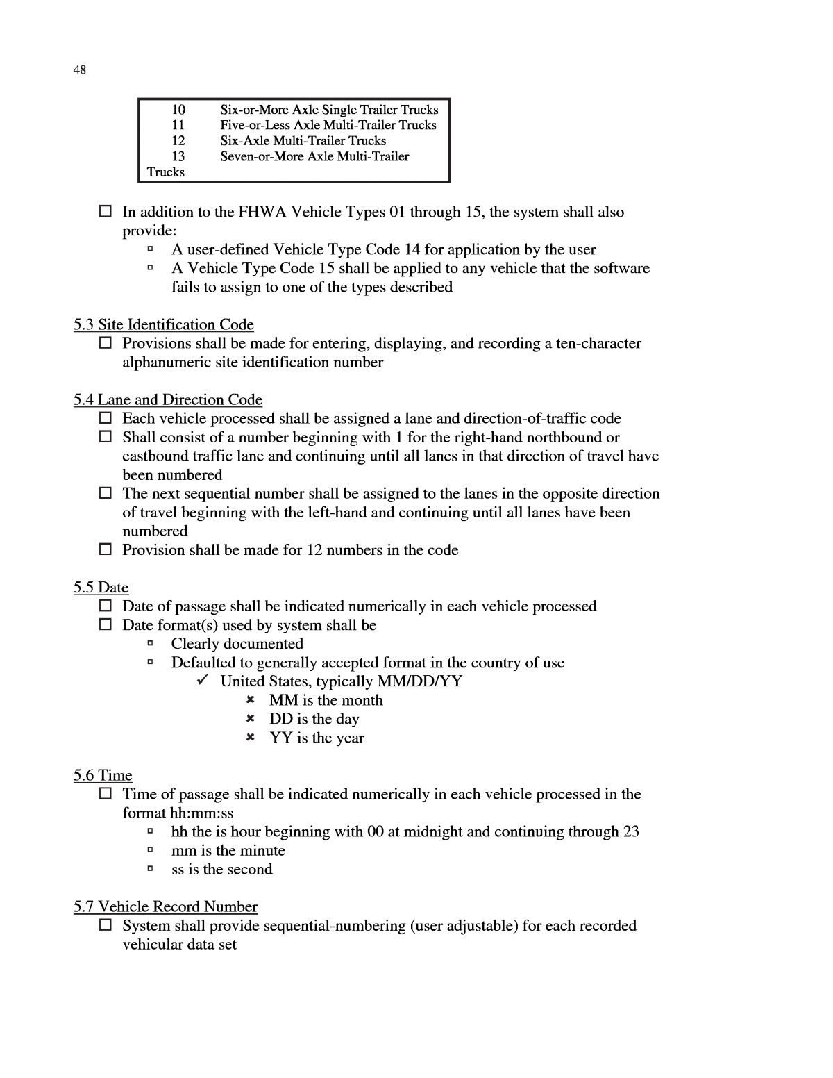
47 speed measurements Sect 5. Performance Requirements 5.1 Accuracy WIM system to be capable of performing all required functions within the following accuracy: Tolerance for 95% Data Item Probability of Conformity Wheel Load +/- 25% Axle-Load +/- 20 % Axle-Group Load +/- 15 % Gross-Vehicle Weight +/- 10 % Speed +/- 1 mph (2km/h) Axle-Spacing +/- 0.5 ft (0.15 m) Required accuracy should be maintained for ambient air temperatures at the WIM site from -20 to 120°F (-28 to 50°C) User shall specify at time of procurement the range of temperatures within which the WIM system must operate properly Vendor shall supply evidence that proposed system is capable of compliance After computation of these data items, no digit shall be retained less than: 100 lb (50 kg) for load or weight 1 mph (2 km/h) for speed 0.1 ft (0.03 m) for axle spacing 5.2 Vehicle Class Vehicles shall be classified according to axle arrangement Vendor shall incorporate software within each system for using the available WIM-system axle-count and axle-spacing information for estimating FHWA Vehicle Types described in TMG Axle-spacing values used for this process shall be associated with each vehicle classified via the software The values shall be: made readily available to the user easily modifiable by means provided to the user FHWA Vehicle Type to be indicated by the 2-Digit Code as follows: 2-Digit Brief Description Code 01 Motorcycles 02 Passenger Cars 03 Other Two-Axle, Four-Tire Single Unit Vehicles 04 Buses 05 Two-Axle, Six-Tire, Single Unit Trucks 06 Three-Axle, Single Unit Trucks 07 Four-or-More Axle Single Unit Trucks 08 Four-or-Less Axle Single Trailer Trucks 09 Five-Axle Single Trailer Trucks
10 Six-or-More Axle Single Trailer Trucks 11 Five-or-Less Axle Multi-Trailer Trucks 12 Six-Axle Multi-Trailer Trucks 13 Seven-or-More Axle Multi-Trailer Trucks In addition to the FHWA Vehicle Types 01 through 15, the system shall also provide: A user-defined Vehicle Type Code 14 for application by the user A Vehicle Type Code 15 shall be applied to any vehicle that the software fails to assign to one of the types described 5.3 Site Identification Code Provisions shall be made for entering, displaying, and recording a ten-character alphanumeric site identification number 5.4 Lane and Direction Code Each vehicle processed shall be assigned a lane and direction-of-traffic code Shall consist of a number beginning with 1 for the right-hand northbound or eastbound traffic lane and continuing until all lanes in that direction of travel have been numbered The next sequential number shall be assigned to the lanes in the opposite direction of travel beginning with the left-hand and continuing until all lanes have been numbered Provision shall be made for 12 numbers in the code 5.5 Date Date of passage shall be indicated numerically in each vehicle processed Date format(s) used by system shall be Clearly documented Defaulted to generally accepted format in the country of use United States, typically MM/DD/YY MM is the month DD is the day YY is the year 5.6 Time Time of passage shall be indicated numerically in each vehicle processed in the format hh:mm:ss hh the is hour beginning with 00 at midnight and continuing through 23 mm is the minute ss is the second 5.7 Vehicle Record Number System shall provide sequential-numbering (user adjustable) for each recorded vehicular data set 48
49 5.8 Wheelbase System shall compute wheelbase as the sum of all axles spacings between centers of the front-most and the rear-most on the vehicle or combination that have tires in contact with the road surface at time of weighing Value rounded before displaying or recording Integer value in feet, or Nearest 0.1 m 5.9 ESALS System shall compute Equivalent Single-Axle Loads (ESALs) using AASHTO axle load equivalency factors For single, tandem, and triple axles For flexible or rigid pavements User selected System shall compute total ESALs for each vehicle or vehicle combination Data prepared for display as part of each vehicle record Displayed value rounded to two significant digits following decimal Presented in following format: FESAL = for flexible pavements user adjustable parameters for serviceability and value for structural number RESAL = for rigid pavements user adjustable parameters for serviceability and value for thickness of slab Refer to actual Standard Specification document for details on requirements pertaining to ESALs 5.10 Violations System shall determine vehicle violation(s) in accordance with all user-set parameters A 2-character violation code shall be used for each detected violation and shall be included in the displayed data (see following example): Violation Code Wheel Load WL Axle Load AL Axle-Group Load AG Gross-Vehicle Weight GV Bridge-Formula Load BF Over Speed OS Under Speed US Provision for user to define up to 15 violation codes Optional- user specified feature(s) calling attention to any data items in violation of user-set limits, such as flashing, underlining, bold facing, or audio 5.11 Acceleration Non-applicable to Type I system 5.12 User-Assignable Code
Provision to allow manual entry of user-assignable three-digit code into any vehicular data set prior to recording 5.13 Tire-Force Sensor Magnitude of the signal to be the same (within tolerance) for a given applied tire force regardless of the lateral position of the tire(s) within the lane 5.13.1 Vendor shall certify the testing and performance of every sensor prior to installation (refer to actual Standard Specification document for details on this requirement) USER REQUIREMENTS and TYPE-APPROVAL TESTING The Specifications include âSite Conditionsâ under 6.1 and âType-Approval Testâ under 7.2. The provisions of these sections are not included in this version of the checkoff list (other than the âCalculationâ provisions of 7.2.7 referenced under 7.5 and 7.6). Unless a user contemplating procurement of WIM system equipment has thorough knowledge of the performance of available equipment which may otherwise appear to meet procurement specifications, such user should fully evaluate the provisions of 6.1 and 7.2 for inclusion in the equipment procurement specifications. Attention is directed to 6.4.1, Implications of a Type-Approval Test, which notes that if a WIM equipment vendor does not provide evidence of previous type-approval testing, the user will not be assured of the capability of the system and shall either require conduct of a Type- approval Test (expenses to be negotiated) wherein the user shall provide appropriate site conditions (see 6.1), or reach an agreement with the vendor before the on-site acceptance test begins as to the specific, quantified tolerance values that will be acceptable if the site conditions provided by the user do not meet or exceed those given in 6.1. CALIBRATION AND ON-SITE ACCEPTANCE TESTING Sect 7 Test Methods for WIM System Performance 7.1.1 Apparatus for Weighing Static Vehicles All weighing apparatus shall be certified as meeting the applicable maintenance tolerance specified in NIST Handbook 44 within 30 days prior to use When system required to meet accuracy requirements for wheel loads, the corresponding reference tire-load values shall be determined with either: Wheel-load weighers Required minimum number of wheel-load weighers is 2 Preferred minimum number of wheel-load weighers is 6 Must meet the respective tolerance specification of NIST Handbook 44 Axle-load scale or multi-platform vehicle scale that has approaches and aprons adjacent to the load-receiving platforms Refer to actual Standard Specification document for details on requirements pertaining to wheel weighing 50
51 When Type I system exempted from meeting accuracy requirement for wheel loads, reference tire-load values shall be obtained by using either: Axle-load scale Multi-platform vehicle scales Portable axle-load weighers A pair of wheel-load weighers Must meet the respective tolerance specification of NIST Handbook 44 7.1.2 Use of Apparatus for Weighing Static Vehicles Tire-pavement contact surfaces of all tires on the vehicle being weighed shall be within 0.25 in. (6 mm) of a plane passing through the load-receiving surface(s) of the weighing device (s) when any tire-load measurement is made Maximum slope of this plane from horizontal shall be 2 % When system required to meet accuracy requirements for wheel loads, wheel and axle load measured simultaneously using a pair of wheel-load weighers. When Type I system exempted from meeting accuracy requirements for wheel- loads: Axle-load shall be determined by positioning each axle to be weighed either simultaneously or successively on either: An axle-load scale(s) A multi-platform vehicle scale A portable axle-load weigher(s) A pair(s) of wheel-load weighers Axle-group load shall be determined by either: Positioning all axles in the group simultaneously on the required number of weighing devices (preferred method) Successively positioning each axle in the group on a pair of wheel- load weighers or on an axle-load weighing device Gross-vehicle weight shall be the total weight of the vehicle determined by single- draft weighing on a vehicle scale and/or the sum of all wheel loads or axle loads for the vehicle Refer to actual Standard Specification document for details on requirements pertaining to weighing 7.1.3 Procedure for Weighing and Measuring Test Vehicles to Obtain Reference Values Two test vehicles (see 7.5.3) are used. The following procedure shall be applied for obtaining reference load, weight, and axle-spacing values for each of the static test vehicles: 7.1.3.1 Measure the center-to-center spacing between successive axles on each test vehicle and record these data to the nearest 0.1 ft (0.03 m) as axle spacing reference values 7.1.3.2 Weigh each test vehicle a minimum of three times, with brakes released, as described in 7.1.1 and 7.1.2 to measure tire loads for the wheel(s) on each end of every axle on the static vehicle
Move the vehicle completely away from scale or weigher before beginning a new set of tire-load measurements Always approach weighing devices from the same direction for weighing Sum the applicable tire loads to determine wheel, axle, and tandem-axle loads as well as gross-vehicle weight each time the vehicle is weighed 7.1.3.3 For all wheel load, axle-load, tandem-axle-load, and gross-vehicle weight values that resulted from weighing each test vehicle three or more times, calculate: arithmetic mean difference, in percent, from the mean of each individual value used in calculating the respective mean 7.1.3.4 Compare percent differences from the mean to the following specified limits for each applicable load or weight value for each test vehicle: Gross-vehicle weight = +/- 2% Tandem-axle load = +/- 3% Axle load = +/- 4% Wheel load = +/- 5% 7.1.3.5 If any of the measured or calculated load or weight values exceed the specified range Correct deficiencies in the reference-value weighing process Weigh each test vehicle a minimum of three more times 7.1.3.6 Repeat 7.1.3.5 until the weighing process yields reference-value loads and weights that are within the specified range 7.1.3.7 For reference-value loads and weights against which to compare WIM- system estimates, use the calculated arithmetic mean value that resulted from successfully weighing each test vehicle three or more times for: Wheel load Axle-load Tandem-axle-load Gross-vehicle weight 7.5 Calibration Procedure 7.5.1 Scope Recommended for inclusion in every On-Site Acceptance Test (see 7.6) Shall be conducted by user with cooperation of vendor (or authorized rep) Requires that two loaded, pre-weighed and measured (see 7.1.3) test vehicles each make multiple runs over WIM-system sensors Each lane Specified speeds 7.5.3 Test Unit for Calibration Loading Test unit shall comprise two loaded, pre-weighed, and measured test vehicles that will make multiple runs over the WIM-system in each lane at prescribed speeds One Class 05 One Class 09 52
53 Suspension types deemed by user to be representative of most vehicles of their type operating at the site Leaf spring Air Other Loaded to at least 90% of their respective registered gross-vehicle weight Non-shifting load Approximately-symmetric (side-to-side) load Excellent mechanical condition Special care to ensure that tires on test vehicles in excellent condition Preferably dynamically balanced Inflated to recommended pressures Reference-value weighing and measurement of the two test vehicles shall be in accordance with 7.1.3 7.5.4 Site Conditions Before initial calibration begins, the existing site conditions (see 6.1) in each lane instrumented with WIM sensors shall be described quantitatively and made a matter of permanent record Estimates of the location and magnitude of each observed pavement surface deviation not meeting smoothness requirement Record time and approximate ambient air temperature Beginning of the calibration process During the calibration process End of the calibration process 7.5.5 Procedure The following steps are involved in the on-site calibration process for each instrumented lane: 7.5.5.1 Adjust all WIM-system settings to either Vendorâs recommendations Best estimate of the proper setting based upon previous experience 7.5.5.2 Measure the speed of each test vehicle every time it passes over the WIM- system sensors using method acceptable to both user (or rep) and vendor Calibrated radar speed meter Calibrated by the method recommended by its vendor within 30 days prior to use Wheelbase/time Other 7.5.5.3 Using approved traffic control procedures and other reasonable safety precautions Each test vehicle to make a series of three or more runs over the WIM- system sensors at the minimum and maximum speed specified by the user between 10 and 80 mph (16 and 130 km/h) Maximum specified speed to be less than legal speed limit at site
These two speeds should differ by at least 20 mph (30 km/h) These two speeds should be above and below the average speed of the vehicles operating at the site Each test truck to pass over the sensors three more times at an intermediate speed that is representative of the prevailing truck traffic at the site At each speed One or more runs made with the test vehicle tires near the left-hand lane edge One or more runs made with the test vehicle tires near the right- hand lane edge All other runs made with the test vehicle approximately centered in the lane Record all data, and note the vehicle record number for every run of each test vehicle 7.5.5.4 Calculate the difference in the WIM-system estimate and the respective reference value, expressed in percent (see 7.2.7), for the two test vehicles for each: Speed Wheel-load Axle-load Tandem-axle load Gross-vehicle-weight Axle-spacing A mean value for the differences for each set of values (if applicable, at each speed set point) 7.5.5.5 Make necessary changes to the WIM-system settings that will adjust the mean value of the respective differences for each value to approximately zero (if applicable, at each speed set point) In accordance with vendorâs recommendations 7.6 On-site Acceptance Test 7.6.1 Scope Provides means for determining whether or not an installed new or modified WIM system meets or exceeds specified functional and performance requirements Defines for the user and the vendor the test method that will be applied for evaluation Requires user to quantify and document site conditions that exist when test is conducted Uses two test vehicles for the test loading unit 7.6.3 Procedure Test shall be conducted on-site by user (or rep), in cooperation with the vendor, immediately after a WIM system has been installed or modified. The following steps are required for each instrumented lane: 54
55 7.6.3.1 Calibrate WIM-system and install WIM-system settings Calibrate and install WIM-system settings per 7.5 Use another calibration procedure as agreed upon in advance by both user and vendor 7.6.3.2 With settings agreed upon by both user and vendor installed on WIM system Each of the two test trucks Makes five or more runs over the sensors at an attempted speed approximately 5 mph (8 km/h) less than the maximum speed and makes five or more additional runs at an attempted speed approximately 5 mph (8 km/h) greater than the minimum speed Maximum and minimum speeds those used during calibration At each speed o One or more runs made with test vehicle tires near left-hand lane edge o One or more runs made with test vehicle tires near right-hand lane edge o Other runs made with test vehicle approximately centered in lane Measure the speed of each test vehicle every time it passes over the WIM- system sensors using method acceptable to both user and vendor Calibrated radar speed meter Calibrated by the method recommended by its vendor within 30 days prior to use Wheelbase/time Other Record all data, and note the vehicle record number for every run of each test vehicle 7.6.4 Calculation Calculate percent difference (error) of WIM data items (7.2.7) for 20 or more runs of the test vehicles Five or more runs at two speeds by two vehicles Compare the functions and performance of the WIM system with all specification requirements, including speed and axle spacing Section 4 for Type I functions Section 5 for Type I performance tolerances 7.6.5 Interpretation of Test Results and Report Declare that the WIM-system was dysfunctional or inaccurate if either: Any specified data-collection feature, data-processing feature, or option of the Type I system described in Section 4 is not demonstrated to function properly More than 5 % of calculated differences for any applicable data item resulting from all passes of the two test vehicles exceeded the Type I tolerance specified in Section 5.
